20
IM FG410-01JA
3. PANELS AND I/O TERMINALS
When not using control input for multi-I/O connector, it is recommended to
disable control input to prevent malfunction due to external noise.
p. 98
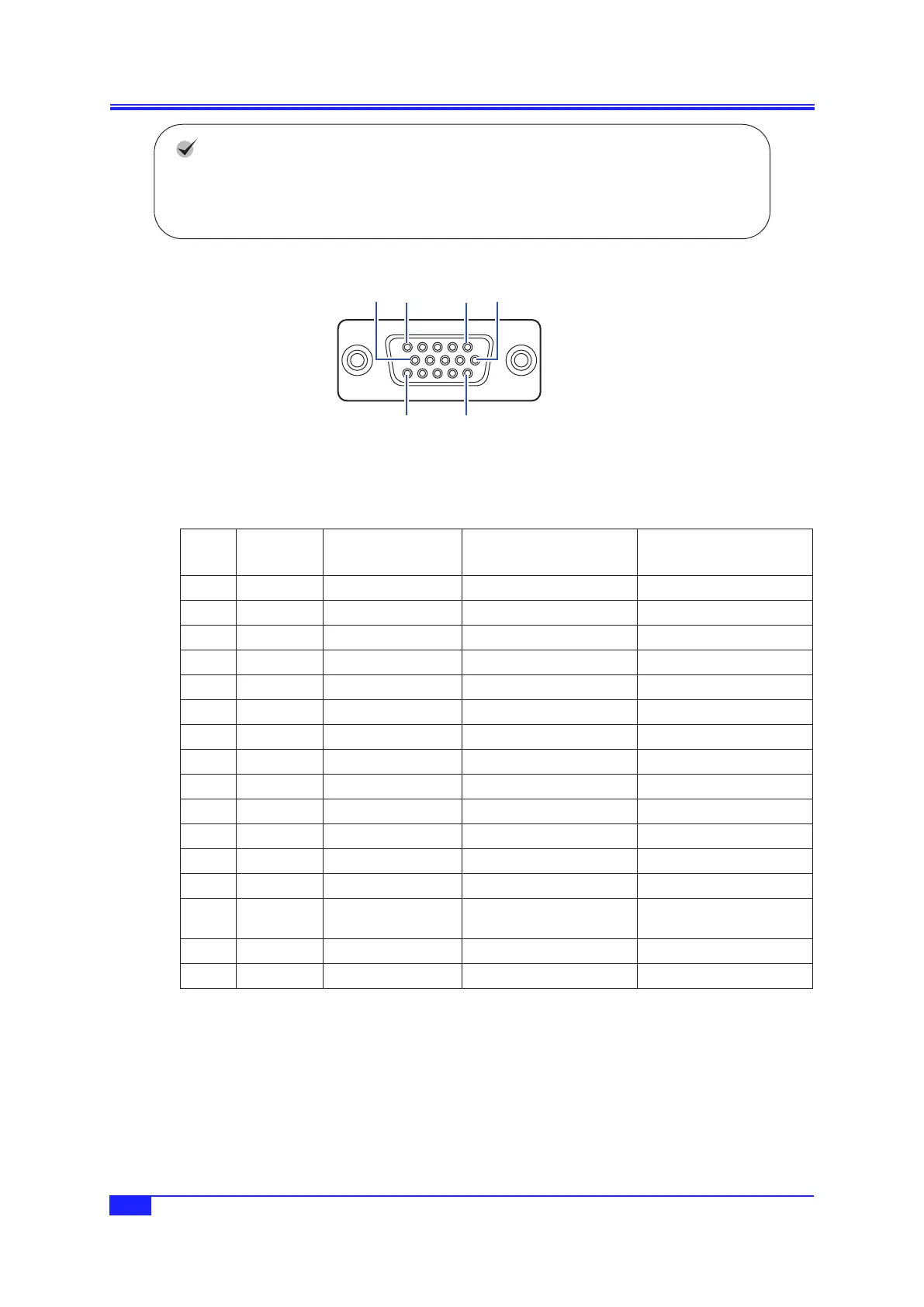
10 5 1 6
15 11
Figure 3-5. Multi-I/O Connector Pin Assignment
Table 3-2. Multi-I/O Connector Function Allocation
Pin
No.
I/O
SweepOscillation
Mode
SequenceOscillation
Mode
OptionCableColorand
Marking
1 Output Not used Step sync code D0 (LSB) Light brown Black■
2 Output Not used Step sync code D1 Light brown Red■
3 Output Not used Step sync code D2 Yellow Black■
4 Output Not used Step sync code D3 (MSB) Yellow Red■
5 Output Not used Not used Bright green Black■
6 GND – – Bright green Red■
7 GND – – Gray Black■
8 GND – – Gray Red■
9 Reserved Leave unconnected Leave unconnected White Black■
10 GND – – White Red■
11 Input Not used Sequence event branch Light brown Black■■
12 Input Sweep hold/resume Sequence hold/resume Light brown Red■■
13 Input Sweep stop Sequence stop Yellow Black■■
14 Input Sweep start Sequence start or state
branch
Yellow Red■■
15 Input Not used Not used Bright green Black■■
Shell – – – Bright green Red■■
Note +5 V is output for testing purposes during production to pin No. 9. This pin is not designed for use by users. Leave this
pin unconnected, as its use may cause the operation of the equipment to become unstable.
 Loading...