175
FORM 160.54-M1
ISSUE DATE: 10/25/2019
JOHNSON CONTROLS JCI COMPANY CONFIDENTIAL
19
SECTION 19 - COMMUNICATIONS
The complete description of the E-Link Gateway In-
stallation Instructions are available in form P/N 24-
10404-9 II. This form can be obtained from the John-
son Controls Portal under Equipment Communications
and Integration in the Documents Library or ordered
from Baltimore Parts Center.
The E-Link Gateway is an optional printed circuit
board that provides an interface between the OptiV-
iew Control Center and the BAS or other selected net-
works. It can be mounted on the upper corner of the
left wall of the OptiView Control Center or in its own
enclosure in a remote location.
If installed in the OptiView Control Center, the E-Link
Gateway is powered by +12 VDC from the microboard.
The E-Link Gateway communicates with the mi-
croboard COM 4B communications port via an RS-
232 interface. As shown in Figure 14 on page 46,
Microboard Program Jumper JP 27 must be placed on
pins 2 and 3 to allow data to be received from the E-
Link Gateway.
If the remote device that is connected to the E-Link
Gateway is going to provide remote Start/Stop signals,
Remote Leaving Chilled Liquid Temperature and/
or Remote Current Limit Setpoint Resets, the Con-
trol Source must be set to ISN on the OPERATIONS
Screen. Otherwise, communications will take place in
any Control Source Mode.
In operation, the microboard provides chiller pres-
sures, temperatures and status to the E-Link Gate-
way in response to requests from the E-Link Gate-
way. Microboard status LED’s illuminate when the
microboard transmits and receives data on COM 4B.
Green LED CR13 (RX4) illuminates when data is be-
ing received from the E-Link Gateway. Red LED CR12
(TX4) illuminates when data is being transmitted to the
E-Link Gateway. Similar LED’s on the E-Link Gate-
way annunciate data transfer to/from the microboard.
If there is a communications problem between the
microboard and E-Link Gateway, use the LED’s de-
scribed above to analyze the problem. The COM 4B
Loop-back test can be used to verify operation of the
microboard COM 4B communications port. See SEC-
TION 34 - DIAGNOSTICS AND TROUBLESHOOT-
ING of this manual.
J2
7
6
9
J21
1
2
TB4
RX2
TX2
J1
1
2
TB1
2
3
4
TO BAS
LAN
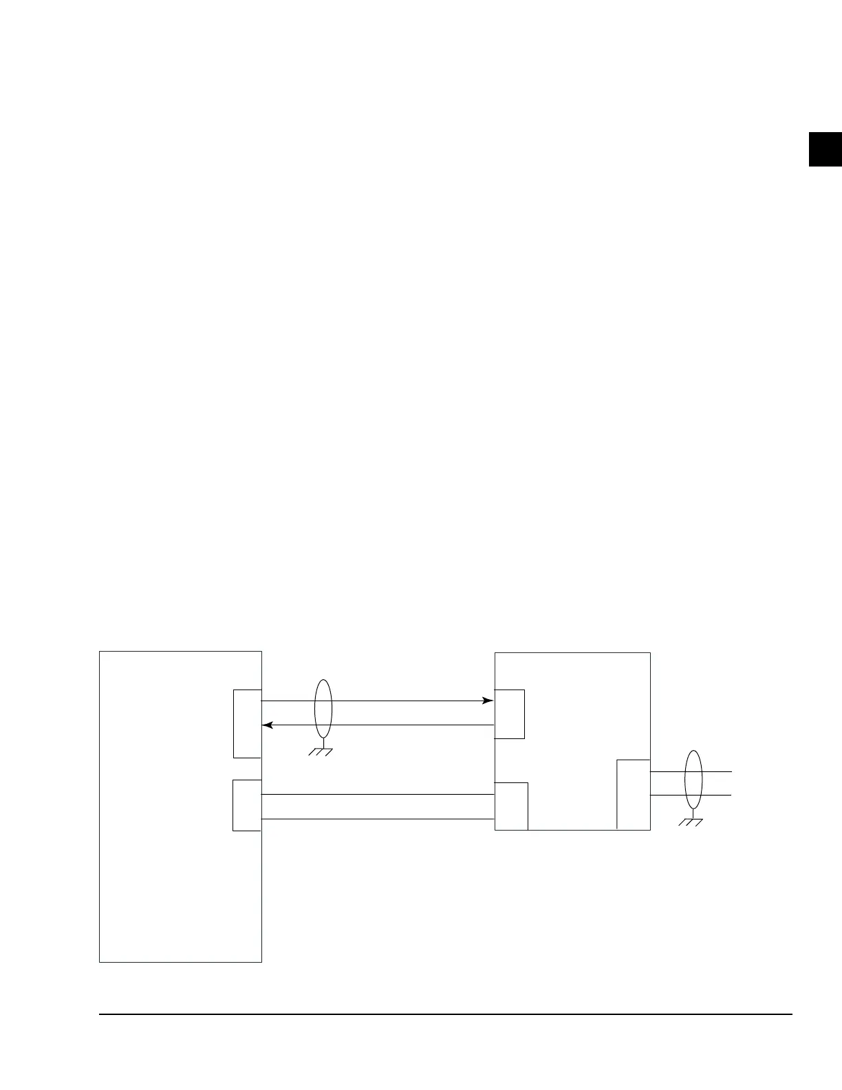
MICROBOARD
E-LINK GATEWAY
RS-485
+
-
G TX
G RX
TX
RX
+ 12VDC
GND
FIGURE 77 - E-LINK GATEWAY INTERFACE BLOCK DIAGRAM
LD06511

 Loading...


