319
SECTION 34 - DIAGNOSTICS AND TROUBLESHOOTING
FORM 160.54-M1
ISSUE DATE: 10/25/2019
JOHNSON CONTROLS JCI COMPANY CONFIDENTIAL
34
From To
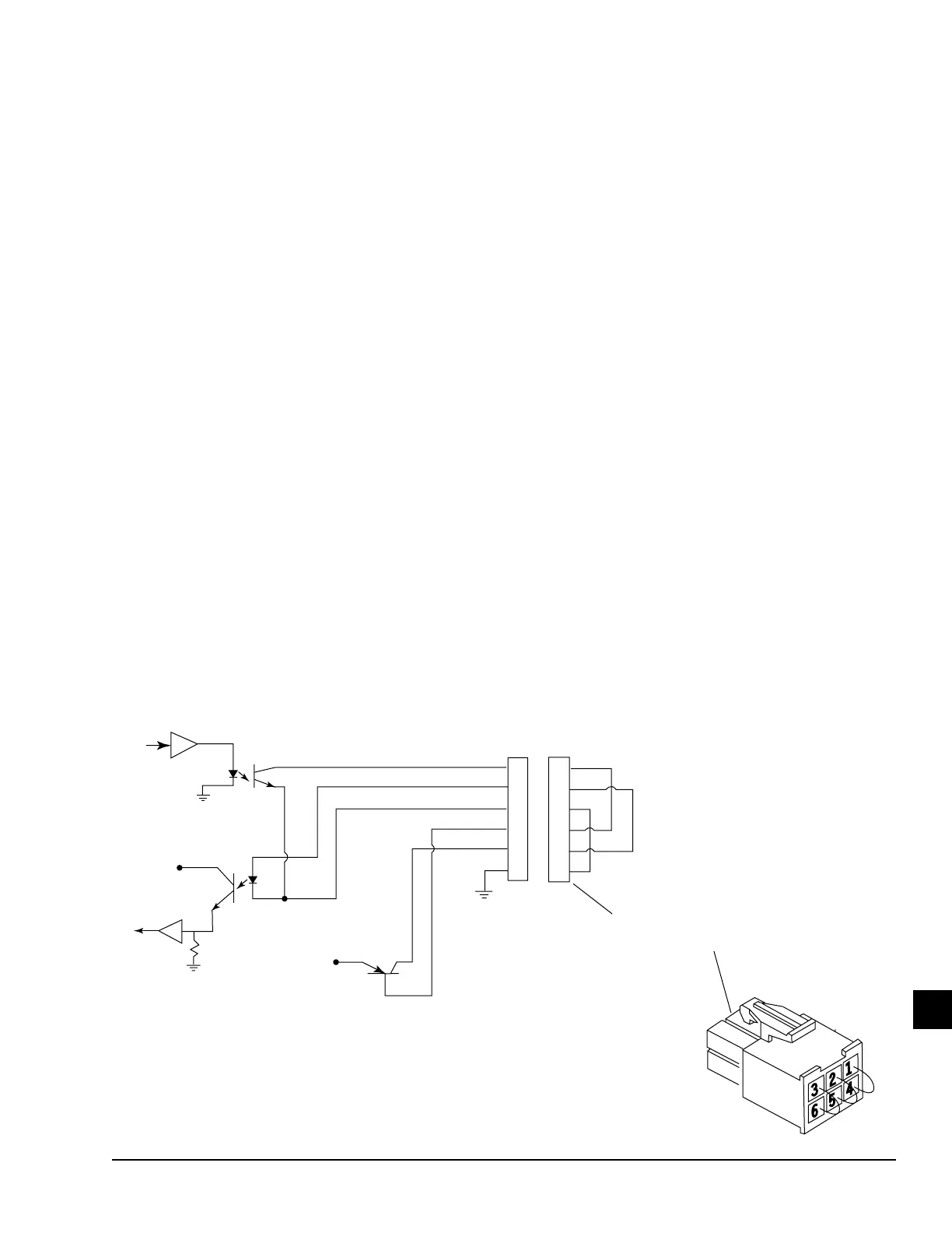
COM 5 J15-1 (TX) J15-4
J15-2 (RX) J15-5
J15-3 (Common) J15-6
Make individual wire connections or use YORK loop-
around diagnostic connector 025-33778-000 as de-
picted in Figure 115 on page 319 This connector is
available from the Baltimore Parts Center.
2. After connecting appropriate loop-back connec-
tions above, press the appropriate key to initiate
the desired test. An LED will illuminate indicat-
ing the test is in progress. If it is desired to termi-
nate the test, press the CANCEL TEST key. Test
data is sent from an output to an input as described
below. At the completion of each test, if the data
received matches the data sent, the serial port op-
erates properly and PASS is displayed. Otherwise,
FAIL is displayed, indicating the serial port is
defective. A FAIL result would be indicative of a
defective Microboard. The following is a descrip-
tion of each test.
COM 1 – Two tests are performed. Test data is
sent from TX (J2-4) to RX (J2-3) at 9600 Baud
and DTR (J2-5) is set to a Logic High level and
read at DSR (J2-2). If any test fails, COM 1 tests
are terminated.
COM 2 – Three tests are performed. Test data
is sent from TX (J13-5) to RX (J13-3) at 19200
Baud. DTR (J13-7) is set to a Logic High and read
at DSR (J13-2) and DCD (J13-1). RTS (J13-4) is
set to a Logic High and read at CTS (J13-6) and
R1 (J13-8). If any test fails, COM 2 tests are ter-
minated.
RS-485 (COM 2 and 4a) – Software version
C.OPT.01.23.307 (and later) only. Test data is
sent from COM 2 RS-485 port to COM 4a RS-
485 port at 19200 Baud. Test data is then sent
from COM 4a to COM 2 at the same rate. If
either test fails, the test is terminated.
RS-485 (COM 3 and 4a) – Test data is sent from
COM 3 RS-485 port to COM 4a RS-485 Port at
19200 Baud. Test data is then sent from COM 4a
to COM 3 at the same rate. If either test fails, the
test is terminated.
COM 4b – Test data is sent from GTX (J2-7) to
GRX (J2-6) at 19200 Baud.
COM 5 – Test data is sent from TX (J15-1) to
J15-4 at 1200 Baud. This output turns the mi-
croboard’s loop-around test transistor on and off,
applying 0 to +5 VDC pulses from J15-5 to RX
(J15-2) input.
3. After all desired tests have been performed, press
the DIAGNOSTICS key to return to the MAIN
DIAGNOSTICS Screen.
FIGURE 115 - MICROBOARD - COM 5 SERIAL DATA PORT
TRANSMIT
RECEIVE
+5VDC
LOOP-AROUND DIAGNOSTIC CONNECTOR
YORK PIN 025-33778-000
INSTALL TO PERFORM DIAGNOSTIC
+5VDC
LOOP-AROUND TEST
J15
1
2
3
4
5
6
1
2
3
4
5
6
TX
RX
COMMON
IN
OUT
LD04250

 Loading...


