PTO Gear Selection Leve
Important: Always use the clutch when engaging or disengaging the PTO or changing PTO
speed. Let the PTO driven implement come to a complete stop before changing.
Operation of the Hydraulic Circuit
Caution: When working with the 3-point linkage, keep well clear of the operating radius of the
lift arms and any attached implement. This is to avoid the risk of injury in the case of incorrect
manoeuvres.
Position Control
Implements can be raised and lowered with the hydraulic position control lever and can be stopped at any
position by stopping the lever.
To ensure a consistent working depth the adjustable stop can be set to ensure that the implement returns to
the same depth every time.
To raise the implement: Pull the lever back.
To lower the implement: Push the lever forward.
WARNING: After finishing work, always lower the implement to the ground and switch off the
en
ine. A
l
the
arkin
brake to
revent in
uries and accidents
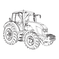
Your tractor is equipped with 2 Speed PTO to suit range o
applications and conditions.
1 - PTO Shift Lever
HODP071
MODEL POSITION
1st 2nd 3nd
HORTUS
CL65 / HS65
540 750 1,000
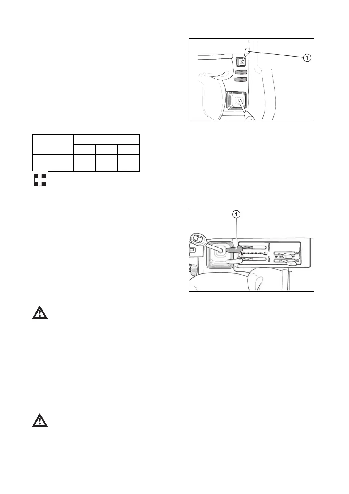
The external and internal hydraulic circuits are driven by
a engine-driven hydraulic pump and controlled by a lever
located next to the driver.
1. Position control lever
HODP072
DESCRIPTION OF TRACTOR CONTROLS

 Loading...