Z8
®
CPU
User Manual
UM001604-0108 External Interface
139
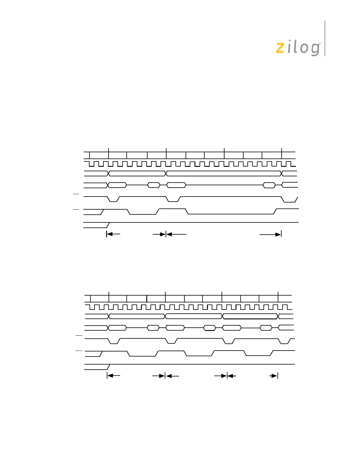
the current instruction, the opcode of the next instruction is fetched. Instruction pipelining
is displayed in Figure 131.
Figure 131 and Figure 132 on page 139 display typical instruction cycle timing for
instructions fetched from memory. For those instructions that require execution time
longer than that of the overlapped fetch, or reference program or data memory as part of
their execution, the pipe must be flushed.Figure 131 and Figure 132 on page 139 assume
the XTAL ÷ 2 clock mode is selected.
Figure 131. Instruction Cycle Timing (1-Byte Instructions)
Figure 132. Instruction Cycle Timing (2- and 3-Byte Instructions)
T1 T2
T3
T3
T1
DS
AS
R/W
T1
T2
T2
Fetch 1st Byte
T3
M1
M2
M3
A15–A8
A15–A8
A15–A8
A7–A0
A7–A0
A7–A0
A7–A0
A7–A0
Fetch 1st Byte Of Next Instruction
*
Port inputs are strobed during T2, which is two internal system clocks
before the execution cycle of the current installation
Clock
T1 T2
T3
T3
T1
DS
AS
R/W
T1
T2
T2
Fetch 1st Byte
T3
M1
M2
M3
A15–A8
A15–A8
A15–A8
A7–A0
A7–A0
A7–A0
A7–A0
A7–A0
Fetch 2nd Byte
Fetch 3rd Byte
Fetch 1st Byte (1- or 2-Byte Instruction)
(3-Byte Instruction)
A15–A8
A7–A0
A7–A0
Clock
*
Port inputs are strobed during T2, which is two internal system clocks before
the execution cycle of the current instruction.

 Loading...