Z8
®
CPU
User Manual
UM001604-0108 Instruction Description
245
Test Under Mask
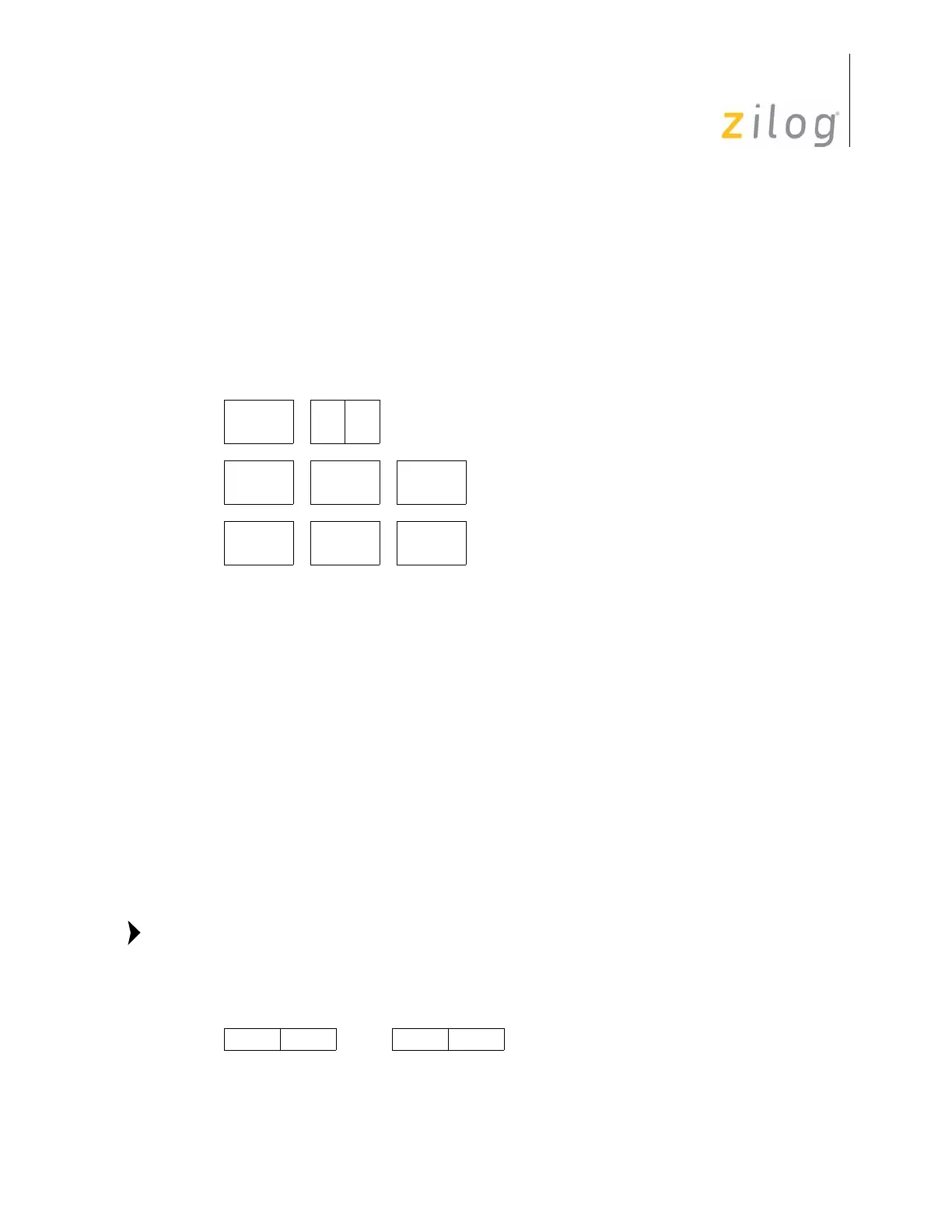
Syntax
TM dst, src
Instruction Format
Operation
dst AND src
This instruction tests selected bits in the destination operand for a 0 logical value. The bits
to be tested are specified by setting a 1 bit in the corresponding bit position in the source
operand (the mask). The TM instruction ANDs the destination operand with the source
operand (the mask). The Zero (Z) Flag can then be checked to determine the result. If the
Z Flag is set, then the tested bits were 0. When the TM operation is complete, the destina-
tion and source operands still contain their original values.
Address modes R or IR can be used to specify a 4-bit Working Register. In this format, the
source or destination Working Register operand is specified by adding
1110b (Eh) to the
high nibble of the operand. For example, if Working Register
R12 (CH) is the destination
operand, then
ECh is used as the destination operand in the Op Code.
Cycles
OPC
(Hex)
Address Mode
dst src
OPC dst src
672r r
673r lr
OPC src dst
10 74 R R
10 75 R IR
OPC dst src
10 76 R IM
10 77 IR IM
Flag Description
Z Set if the result is zero; cleared otherwise.
S Set if the result bit 7 is set; cleared otherwise.
V Always reset to 0.
D Unaffected
H Unaffected
Esrcor Edst
Note:

 Loading...