Z8
®
CPU
User Manual
UM001604-0108 Clock
30
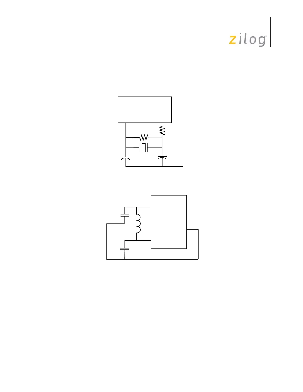
Depending on operation frequency, the oscillator may require the addition of capacitors
C1 and C2 (displayed in Figure 18). The capacitance values are dependent on the manu-
facturer’s crystal specifications.
In most cases, the R
D
is 0 Ω and R
F
is infinite. It is determined and specified by the crystal/
ceramic resonator manufacturer. The R
D
can be increased to decrease the amount of drive
from the oscillator output to the crystal. It can also be used as an adjustment to avoid clip-
ping of the oscillator signal to reduce noise. The R
F
can be used to improve the start-up of
the crystal/ceramic resonator. The Z8
®
oscillator already has an internal shunt resistor in
parallel to the crystal/ceramic resonator.
Figure 18. Crystal/Ceramic Resonator Oscillator
Figure 19. LC Clock
XTAL2
Z8
®
CPU
V
SS
XTAL1
C1
C2
R
F
R
D
XTAL2
Z8
®
CPU
V
SS
XTAL1
C1
C2
L

 Loading...