Z8
®
CPU
User Manual
UM001604-0108 Input/Output Ports
79
Vil
(max), pullup or pull-down resistances must be calculated using Ref = R/Rp. For best
case STOP mode operation, the inputs should be within 200 mV of the supply rails.
In output mode, if a port bit is forced into a tri-state condition, the autolatches force the
pad to V
DD
. If there is an external pulldown resistor on the pin, the voltage at the pin may
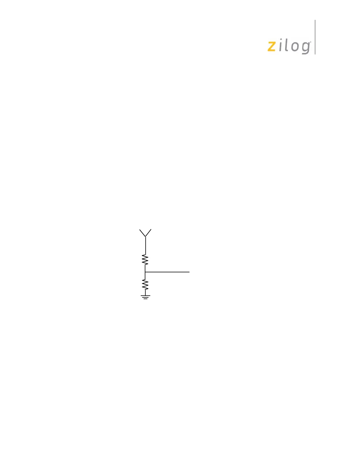
not switch to GND due to the autolatch. As displayed in Figure 67, the equivalent resis-
tance of the autolatch and the external pulldown forms a voltage divider, and if the exter-
nal resistor is large, the voltage developed across it will exceed V
IL
(max). For worst case.
V
IL
(max > V
DD
[R
EXT
÷ (R
EXT
+ R
P
)]
R
EXT
(max) = [(V
IL
(max) ÷ V
DD
) R
P
] ÷ [1—(V
IL
(max) ÷ V
DD
)]
For V
DD
= 5.0 V and I
AO
= 5 µA, V
IH
(max) = 0.8 V:
R
EXT
(max) = (0.16 ÷ 1M) ÷ (1—0.16) = 190 K¾.
Rp increases rapidly with V
DD
, so increased V
DD
will relax the requirement on Rext.
In summary, the CMOS Z8 autolatch inhibits excessive current drain in Z8 devices by
latching an open input to either V
DD
or GND. The effect of the autolatch on the I/O char-
acteristics of the device may be modeled by a current I
AO
and a resistor Rp, whose value is
V
DD
/I
AO
.
Figure 67. Effect of Pulldown Resistors on Autolatches
V
LO
V
IH
(min.)
R
P
R
EXT

 Loading...