The high voltage section of the device starts at the power inlet element. It is designed as a high-current type of a non-
heating device socket to allow different mains cable to be supplied for different countries. 2x 2AT fuses are integrated in
the power inlet element to monitor both mains cables and it provides a 2-way shutdown.
From the power inlet element the mains voltage will be distributed via connecting cables to the mains switch. The mains
switch is designed for mains voltages between 85V to 265 VAC. From there the mains voltage will be distributed over a
line filter electrical components (2x stroko coils and Y-capacitors) and bridge rectifier to the switching-mode power
supply unit.
The PSU generates the necessary voltages for the different electrical circuits of the patient channnel1, channel 2 and for
the User interface. The generated voltages are as following listed
¾ A 200V DC/ 0,15A to generate the therapeutically currents and 15V/ 0,33A for the logical components of the
channel 1(stimulating current& ultrasonic)
¾ A 200V/ 0,075A to generate the therapeutically currents and 15V/ 0,33A for the logical components of the
channel 2 (stimulating current only)
¾ A 12V/1,7A for the user Control (CPU, operating unit, Ethernet, Audio, Display SD-card and the vaco user
signal of 12V, 5V ).
All clearance and creepage distances and electrical strengths are applied in compliance to the requirement in
IEC60601-1.
The above-mentioned voltages are distributed via connecting cable to the mainboard where the different voltages for the
end stage and logical circuits will be generated.
All components (solid state relay, transformers and optocouplers) connected to low voltage and mains voltage are tested
with an electrical isolation of 4 kV and are defined as UL-listed components.
NOTE: Do not use other types then the defined ones.
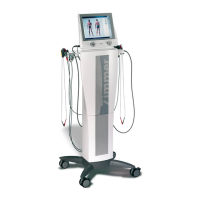
The following figure shows the block diagram of PhySys Edition SD.