Table of Figures
Figure 1. Nightingale Monitoring System ............................................. 1-1
Figure 2. PPM3 Front View .................................................................. 1-3
Figure 3. PPM3 Rear View .................................................................. 1-4
Figure 4. PPM3 Left View .................................................................... 1-5
Figure 5. PPM3 Right View .................................................................. 1-6
Figure 6. Partially Engaged Power Connector ..................................... 1-7
Figure 7. Fully Engaged Power Connector .......................................... 1-7
Figure 8. PPM3 Front Panel ................................................................ 1-8
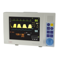
Figure 9. Sample of PPM3 Main Screen ............................................ 1-10
Figure 10. PPM3 Startup Screen ........................................................ 2-4
Figure 11. PPM3 Shutdown Screen .................................................... 2-5
Figure 12. New Patient Screen With Previous Patient ........................ 2-9
Figure 13. Main Screen With No Patient Admitted ............................ 2-10
Figure 14. ECG Waveform and HR Value .......................................... 3-2
Figure 15. Standard AHA Electrode Placement .................................. 3-5
Figure 16. Standard IEC Electrode Placement ................................... 3-6
Figure 17. Paced AHA Electrode Placement ...................................... 3-7
Figure 18. Paced IEC Electrode Placement........................................ 3-8
Figure 19. RR Waveform and Value ................................................... 4-2
Figure 20. SpO
2
Waveform and Value ................................................ 5-2
Figure 21. NBP Value with Interval ..................................................... 6-2
Figure 22. Oridion CO
2
Waveform and Values ................................... 7-3
Figure 23. Integrated Pulmonary Index ............................................... 7-4
Figure 24. Masimo ISA Module With Nomoline ................... 8-1
Figure 25. Masimo IRMA Module With Airway Adapter ...................... 8-1
Figure 26. Nomoline Adpater ‒ Female Luer Lock ............................. 8-2
Figure 27. Snapping IRMA Onto Adapter ...................................... 8-3
Figure 28. Masimo CO
2
Waveform and Values .................................. 8-4
Figure 29. IBP Waveforms and Values ............................................... 9-3
Figure 30. TEMP Value..................................................................... 10-1
Figure 31. Setup HR Menu ............................................................... 11-2
Figure 32. HR/PR Values Sourced From SpO2 or ART ................... 11-3
Figure 33. Setup RR Menu ............................................................... 11-4
Figure 34. Setup SpO
2
Menu ............................................................ 11-5
Figure 35. Setup NBP Menu ............................................................. 11-7
Figure 36. Setup CO
2
Menu With Oridion Capnography................... 11-9
Figure 37. Setup CO
2
Menu With Masimo Capnography ................ 11-10
Figure 38. Setup IBP Menu ............................................................. 11-12
Figure 39. Setup TEMP Menu ........................................................ 11-13