47
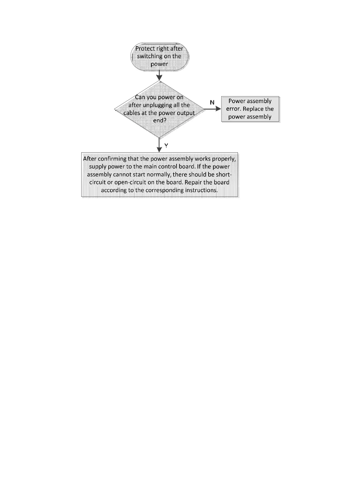
Figure 6-5 Troubleshooting for power-on protection problem
6.4 Main Control Board
6.4.1 Introduction
The main control board consists of analog module, digital module and power drive module; among
which, the analog module conditions and amplifies the signals from the impedance channel and HGB
channel as well as other analog signals like monitoring voltages, and converts them into digital signals
through the A/D converter. The digital module is responsible for the drive and control of mechanical
parts as well as the processing, outputting and communication of data. The power drive follows the
instruction of CPU to drive the motors, valves, pumps and heaters.
6.4.2 Components
The structure of the main control board is illustrated in figure 8-6. It mainly consists of digital circuits
and several ADC circuits for A/D conversion. The digital circuit module is responsible for processing
data, saving and outputting results. Furthermore, as the core of the main control board and even the
whole hardware system, it takes the management and communication job. ADC circuits uses A/D
converters to convert analog value monitoring signals (like WBC, RBC, PLT counts etc.) to digital signals.
The control function of the main control board is realized with a "CPU+FPGA" structure. The main
control board mainly provides the following functions:
A/D conversion