45
printer, keyboard, and barcode scanner) and Ethernet interface. Besides, peripheral interfaces
also include those to the working status indicator and the [Aspirate] key.
6.2 Electrical Connection Diagram
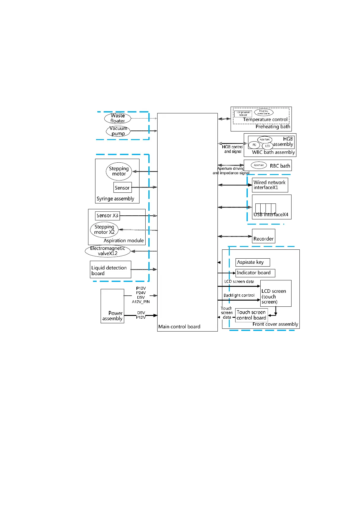
The electrical connection of the analyzer is shown as below:
Figure 6-2 Electrical Connection
6.3 System Problem
Hardware system errors mainly include board errors, cable errors and component errors. The
subsequent sections should have provided troubleshooting methods for most of such errors; but
when the power supply to the hardware system is abnormal (for example, the analyzer cannot be
powered on, or would start self-protect mechanism immediately after being powered on), you need
to start troubleshooting from the system level. Figure 6-3 demonstrates the troubleshooting
procedure for power supply errors. Figure 6-4 displays a power filter locating at the lower part at the
rear of the analyzer. The power filter controls the power supply and frequency filtering of the analyzer.