44
6 Hardware System
The hardware system not only consists of power board, main control board, indicator board,
touch screen control board and liquid detection board, but also the electrified drives and
components (e.g. motors, valves, pumps, sensors, screens, and power filters), as well as the
cables connecting different boards or connecting boards and components.
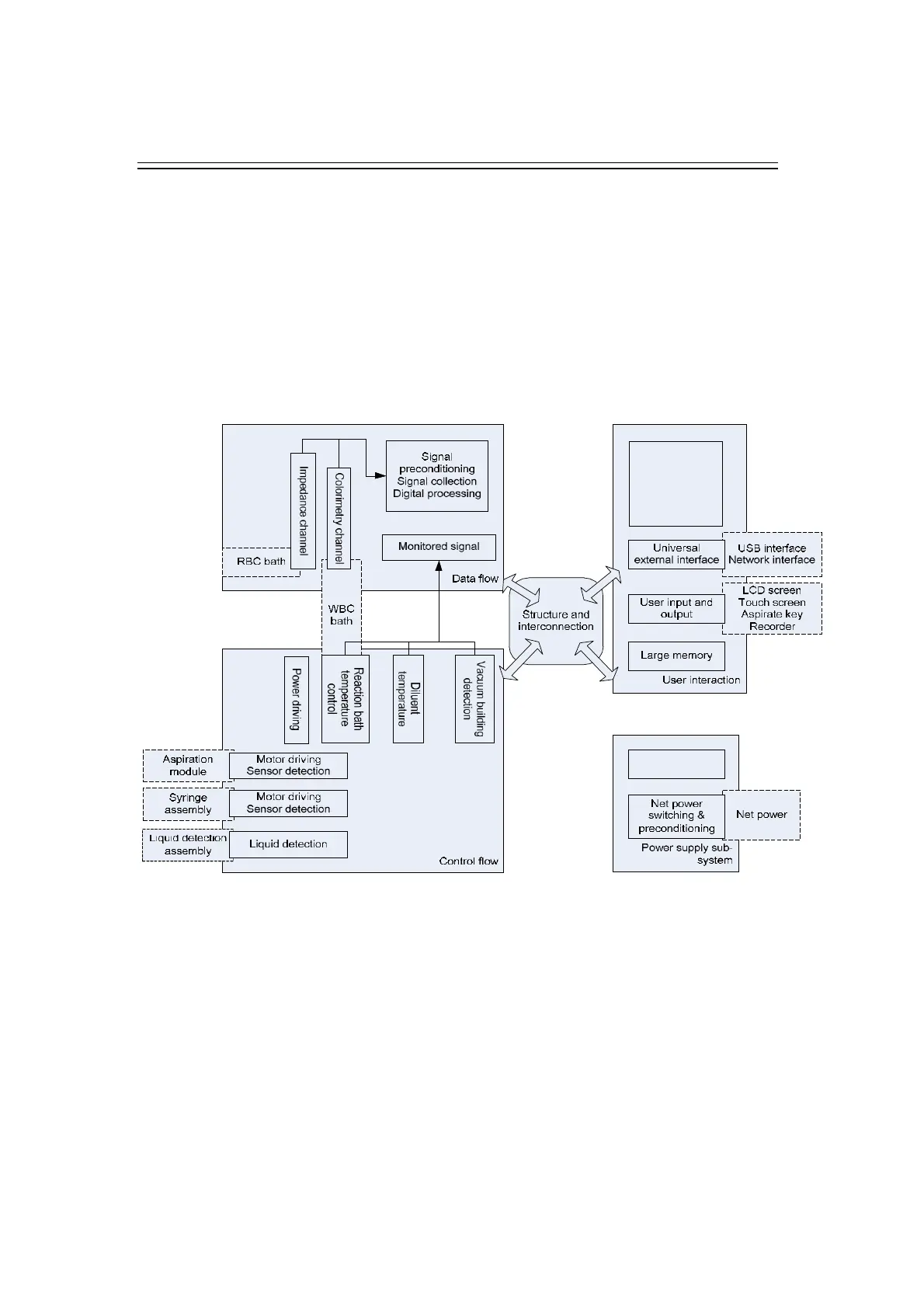
6.1 Hardware System Function Block Diagram
The function block diagram of the hardware system is shown as below.
The hardware system consists of 5 major modules: system power, data flow channel, main
control system, drive parts and peripheral interfaces.
Figure 6-1 Function Block Diagram of the Hardware System
The functions of each module are shown below:
System power: provide power of required specifications to all boards, parts and devices.
Data flow channel: detect, condition, amplify, collect and pre-process signals.
Main control system: collect and process data, display results and store sample information. Besides,
main control system acts as the control and management center which controls and responds to all
other components and devices.
Drives/detectors: control valves, pumps and motors; monitor the photocouplers and other
important parameters; collect information during analysis and send out flags.
Peripheral interfaces: include interfaces to display/touch screen, USB ports (connecting to