63
6.8.2 Components
The indicator board consists of a three color indicator (red, yellow and green) with its control circuit.
You do not need to make adjustment to the indicator board during use.
6.8.3 Indicator Board problem
Table 6-12 Troubleshooting for indicator problem
1.
1. Check whether the main control board works properly (screen
displays normally, and basic operations like sample analysis and
information review can be run properly). If there is any problem,
start troubleshooting for the main control board first;
2.
2. Check whether the cables connecting to the indicator board get
loose or broken. If they get loose, reconnect the cables; if they get
broken, replace it as well as the front panel signal cables;
3.
3. If cable errors can be excluded, replace the indicator board.
6.9 Motors, Photocouplers and Micro-switches
6.9.1 Introduction
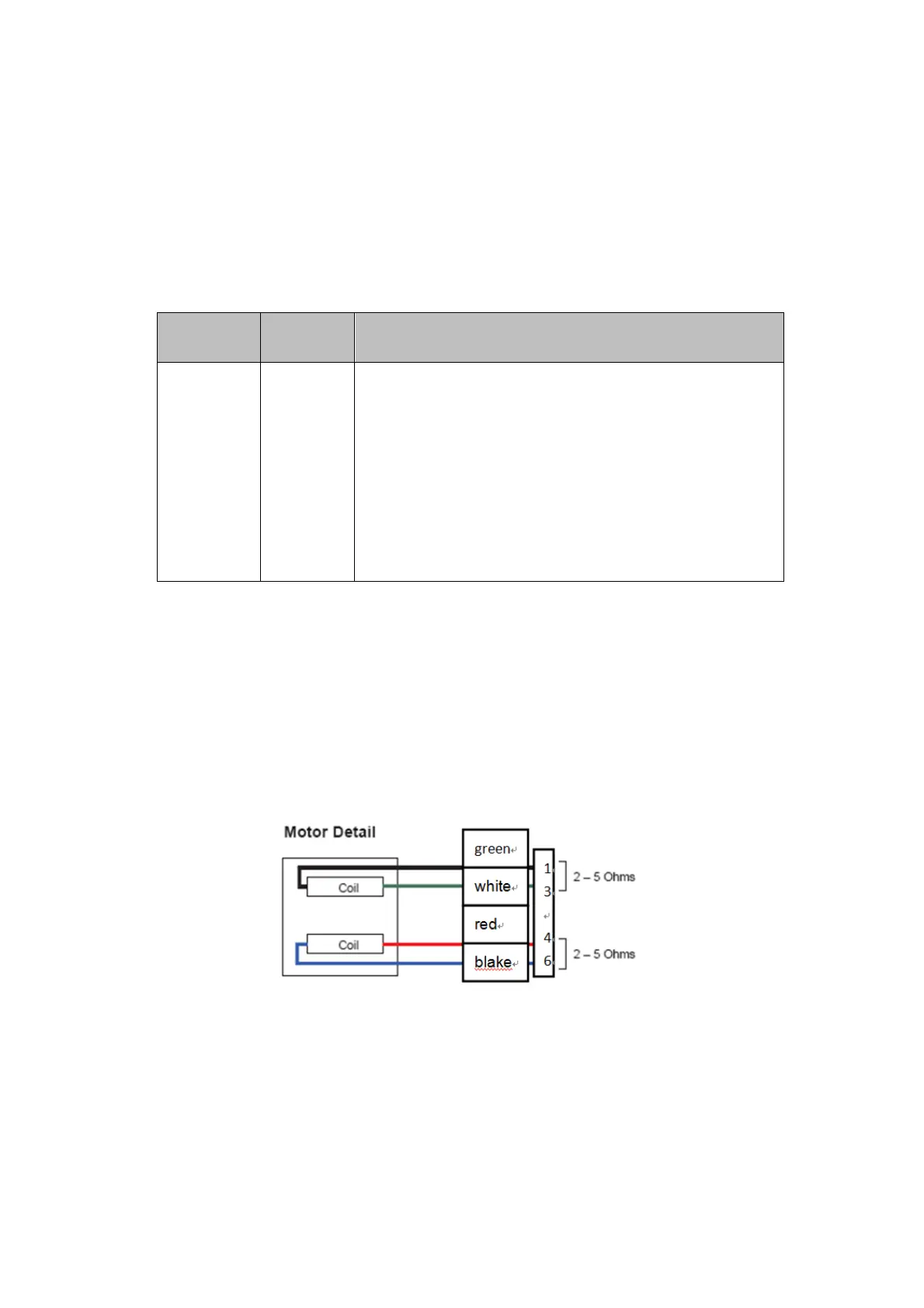
Motors drive the aspiration module and syringe module etc.; photocouplers detect the motor
movements; and micro-switches are used to start analysis process. See below for the illustrations of
motors and photocouplers.
Figure 6-14 Motors illustrations