66
7 Mechanical System
7.1 Introduction to Mechanical Structure
This section demonstrates the positions of major serviceable components in the analyzer so our
service people may find these component quickly to remove or replace them. Figures, pictures
and drawings in this manual are prepared based on Z3.
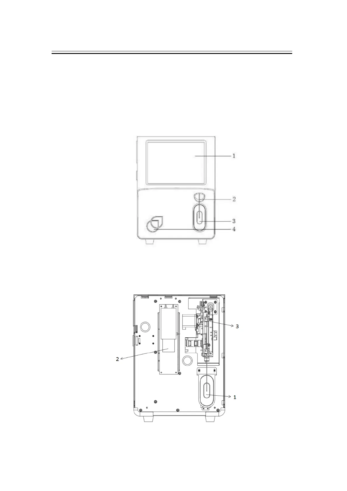
7.1.1 Front of the Analyzer
Figure 7-1 Front of the analyzer
1 ---- Display scree 2---- Sample probe
3 ---- [Aspiration] Key 4----Power/Status indicator
7.1.2 Front of the Analyzer (front cover open)
Figure 7-2 Front of the Analyzer (front cover open)
1 ---- [Aspiration] Key Module 2 ---- Syringe module
3 ---- Sampling Module