13
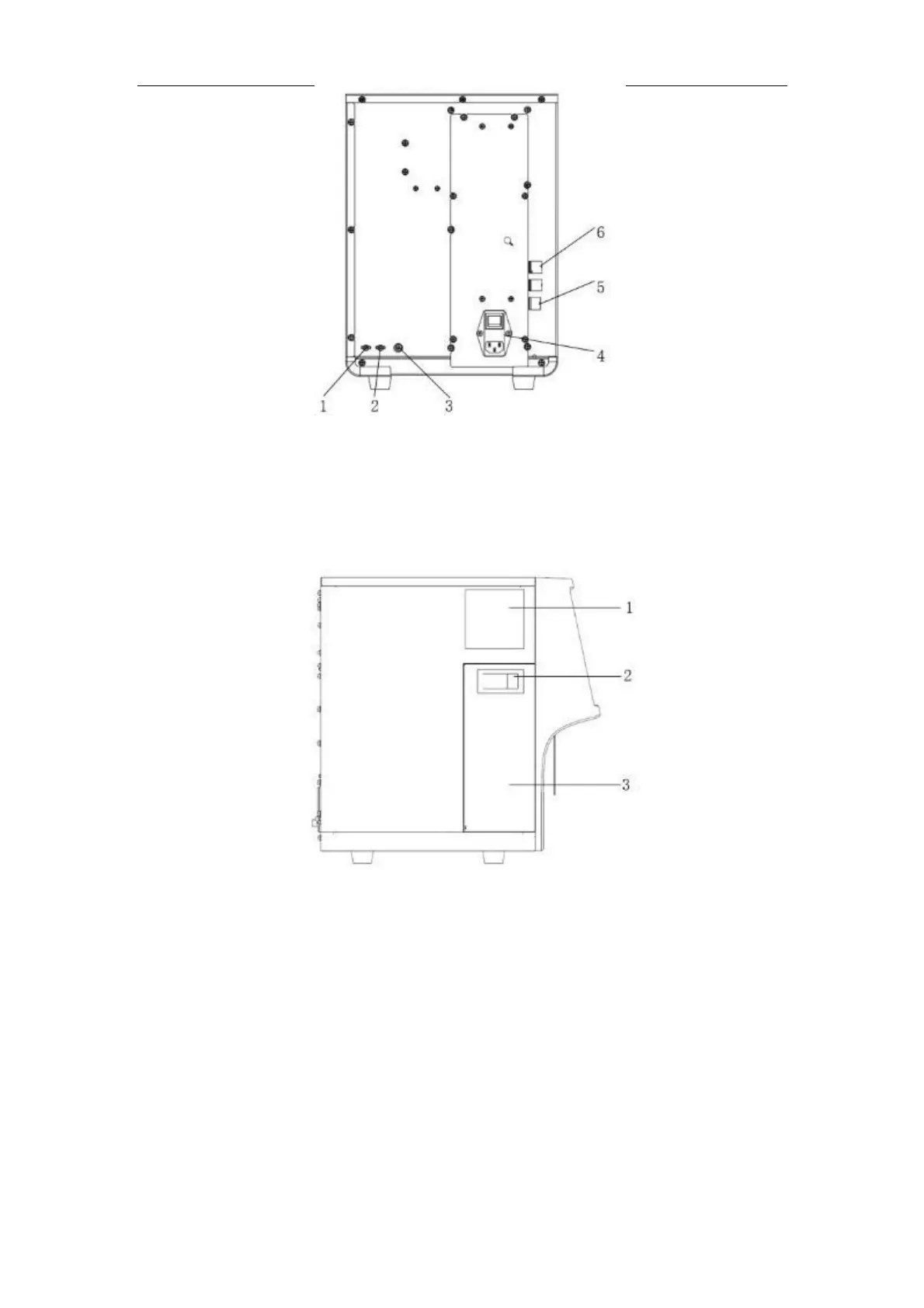
Figure 2-2 Back of the analyzer
1 --- Diluent inlet 2 --- Waste outlet
3 --- Waste sensor connector 4 --- Power input socket
5 --- Network interface 6 --- USB interface
Figure 2-3 Left side of the analyzer
1 --- Built-in recorder 2 --- Locker
3 --- Side door
2.9.1 Main unit
The main unit performs sample analysis and data processing. It is the main part of the instrument.
2.9.2 Power/status indicator
The power/status indicator tells you about the status of the analyzer including ready, running,
error, standby and on/off, etc.