25-18
Displaying and Maintaining IRF
To do… Use the command… Remarks
Display related information of the IRF display irf Available in any view
Display topology information of the IRF display irf topology Available in any view
Display the pre-configurations of all
members of the IRF (The
pre-configuration takes effect after the
reboot of the device.)
display irf configuration Available in any view
Display the master/slave switchover
states of IRF members
display switchover state
[ member-id ]
Available in any view
IRF Configuration Examples
IRF Connection Configuration Example
Network requirements
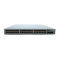
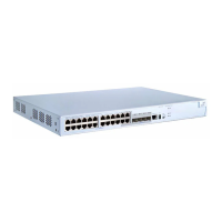
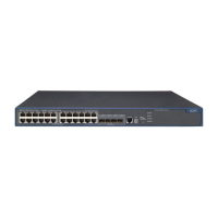
Three Switch 4510G series switches in an IRF form a bus connection. Their member IDs are 1, 2, and
3, as shown in
Figure 26-9.
Figure 26-9 Network diagram for IRF
1
Switch 1
Switch 2
2 43
Switch 3
1
3
2
4
3
1
2
4
Configuration procedure
1) The three devices are not connected. Power them on and configure them separately.
# Configure Switch 1.
<Switch1> system-view
[Switch1] irf member 1 renumber 1
Warning: Renumbering the switch number may result in configuration change or loss.
Continue?[Y/N]:y
[Switch1] irf member 1 irf-port 1 port 2
# Configure Switch 2.
<Switch2>system-view
[Switch2] irf member 1 renumber 2

 Loading...


