22 CHAPTER 2: SWITCHING CONCEPTS AND NETWORK CONFIGURATION EXAMPLES
Deployment of VLANs in a More Complex Network
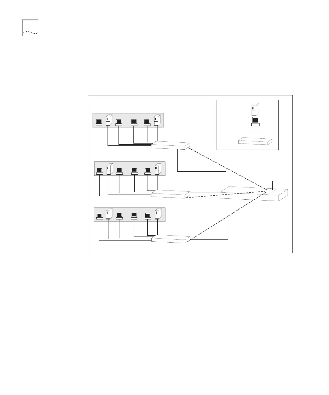
In Figure 5, the Layer 3 Module in Switch D routes packets between
VLANs.
Figure 5 Complex Network with VLANs
Figure 5 shows the same network as Figure 4, but here the LAN has been
divided into VLANs.
Small groups of ports on Switch D have each been assigned to particular
VLANs.
This scenario reduces the load on Switch D, because broadcast and
multicast traffic between devices on each VLAN is not seen by the rest of
the network.
Packets routed
between VLANs
Switch A
Switch B
Switch C
IP Network Address:
Subnet Mask:
VLAN 1
IP Network Address: 192.168.169.0
Subnet Mask: 255.255.255.0
VLAN 2
VLAN 3
IP Network Address: 192.168.170.0
Subnet Mask: 255.255.255.0
192.168.168.0
255.255.255.0
Server
Workstation
Key
Cable
Switch
Layer 3 Module
Switch D