Network Configuration Examples 23
Addition of Multiple VLANs per Switch
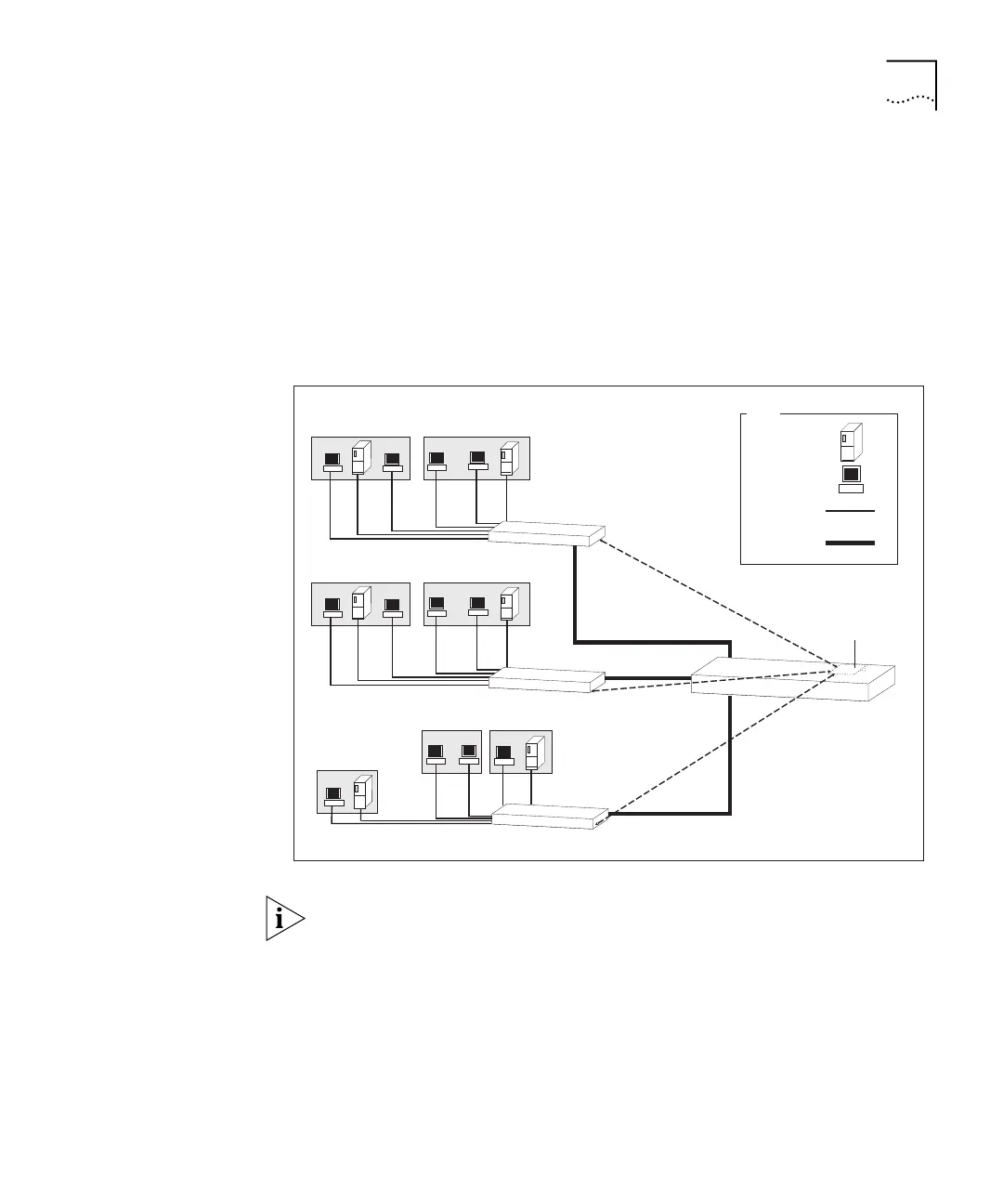
In Figure 6, the Switches are connected by 802.1Q tagged links. 802.1Q
tagged links are links that use the tagging system defined in the IEEE
802.1Q standard to carry traffic for multiple VLANs. Using the 802.1Q
tagged links, the Layer 3 Module can tell Switches A, B and C which
VLAN the packets are destined for. All Switches at the end of the links
receive traffic for all VLANs.
Figure 6 Network Using Multiple VLANs
The Switches could also be connected in a stack using a SuperStack II
Switch Matrix Module. For further information, see the user guide for the
SuperStack II Switch Matrix Module.
Traffic on each VLAN is switched at Layer 2 via Switch D, and routed at
Layer 3 to other VLANs via the Layer 3 Module. For example, traffic from
VLAN 1 on Switch A is switched to VLAN 1 on Switch B via Switch D.
Traffic from VLAN 1 on Switch C to VLAN 2 on Switch C is routed at
Layer 3 through the Layer 3 Module on Switch D.
Packets routed
between VLANs
Switch A
VLAN 3
Subnet mask: 255.255.255.0
192.168.170.0
Switch B
Switch C
VLAN 1
Subnet mask: 255.255.255.0
192.168.168.0
VLAN 2
Subnet mask: 255.255.255.0
192.168.169.0
802.1Q
tagged link
Server
Workstation
Key
Cable
Layer 3 Module
Switch D
VLAN 1
Subnet mask: 255.255.255.0
192.168.168.0
VLAN 2
Subnet mask: 255.255.255.0
192.168.169.0
VLAN 1
Subnet mask: 255.255.255.0
192.168.168.0
VLAN 2
Subnet mask: 255.255.255.0
192.168.169.0