24 CHAPTER 2: SWITCHING CONCEPTS AND NETWORK CONFIGURATION EXAMPLES
Heavy inter-VLAN Traffic
If a particular Switch has a lot of inter-VLAN traffic, you can use a Layer 3
Module in the Switch to route packets between VLANs in one part of the
network, as shown in Figure 7.
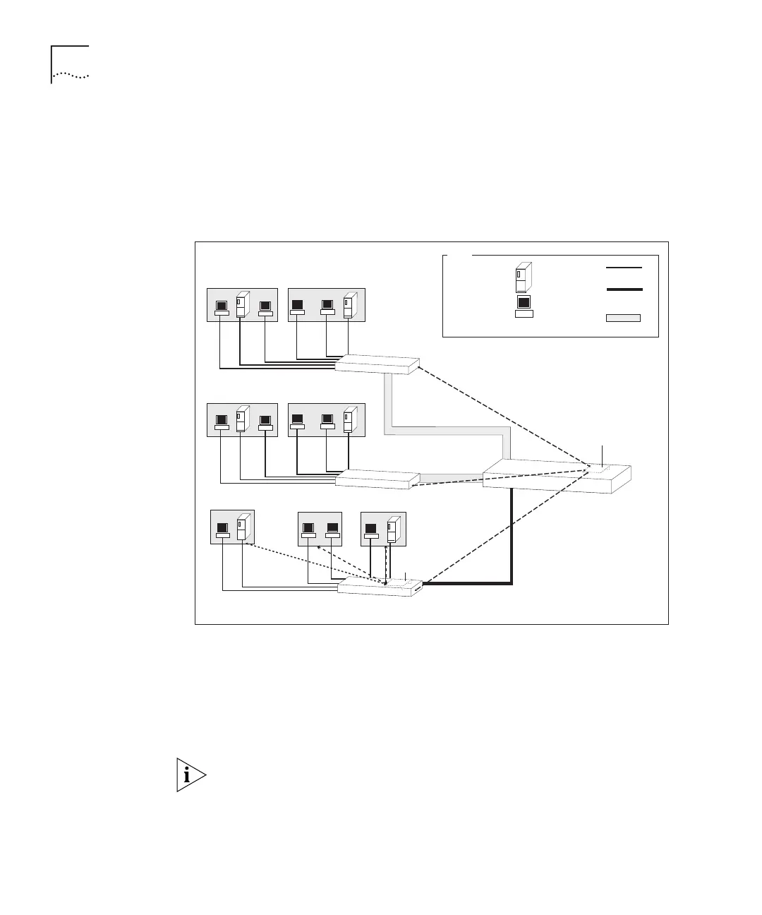
Figure 7 Network Using Multiple Layer 3 Modules
Here there is heavy traffic between the VLANs on Switch C. The addition
of a Layer 3 Module in Switch C allows traffic to be routed to the correct
VLANs, without having to cross the downlink to the Layer 3 Module in
Switch D to be routed. Traffic from a host on VLAN 1 on Switch C,
destined for a host on VLAN 2 of Switch B, is routed in Switch C onto
VLAN 2 and switched at Layer 2 through Switch D to Switch B.
If you have stacked your Switches, install only one Layer 3 Module in the
stack. In Figure 7, Switch A, Switch B and Switch D form a stack, using a
Matrix Module, with Switch C connected via an 802.1Q tagged link. See
“Using the Layer 3 Module in a Switch Stack” on page 25 for more
information about Matrix modules and the Layer 3 Module.
Packets routed
between VLANs
Layer 3
Module
Server
Workstation
Key
Switch A
VLAN 3 192.168.170.0
Subnet mask: 255.255.255.0
Switch B
Switch C
VLAN 1
Subnet mask: 255.255.255.0
192.168.168.0
VLAN 2
Subnet mask: 255.255.255.0
192.168.169.0
VLAN 1
Subnet mask: 255.255.255.0
192.168.168.0
VLAN 2
Subnet mask: 255.255.255.0
192.168.169.0
VLAN 2
Subnet mask: 255.255.255.0
192.168.169.0
VLAN 1
Subnet mask: 255.255.255.0
192.168.168.0
Cable
.1Q Tag
Downlink
Matrix
Downlink
Layer 3 Module
Switch D