99
M512-3 Juggler : User Guide
© 2021 7thSense
Nodes: Connecting Juggler Systems
Show a miniature map of all nodes and the position of the current view.
Make the position of a selected node the viewpoint for any node then selected in the Project
panel.
This toggle button is not enabled until one and only one node is selected. When the position of
that node is pinned, any node then selected centres all nodes around that point. If more than
one node is selected, the viewpoint is disabled again.
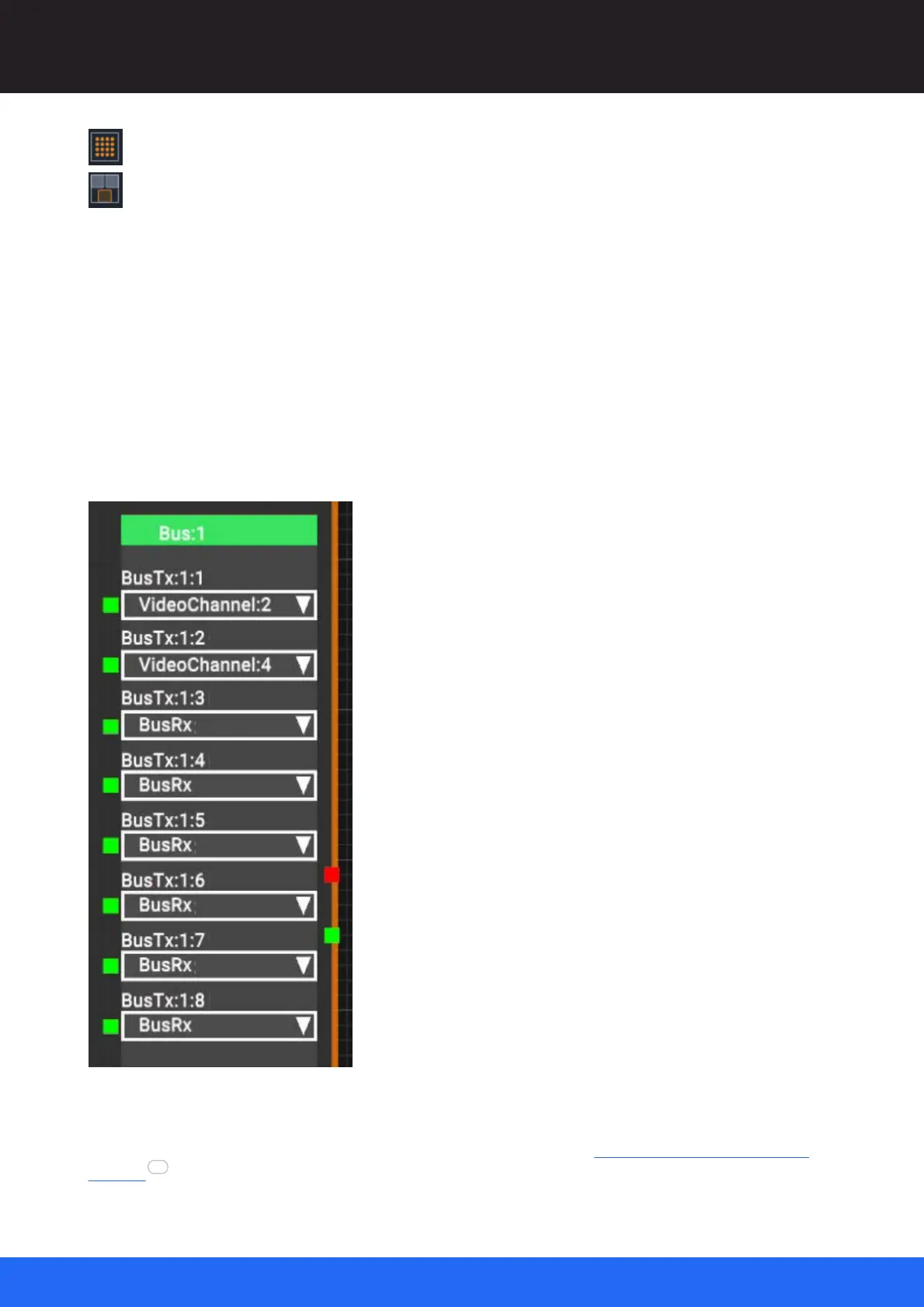
The Juggler bus options
On the side of the Juggler node is the bus block. Jugglers can have one of two optical fibre bus
options: 4-lane (2 × Rx and 2 × Tx video channels) and 8-lane (4 × Rx and 4 × Tx video channels). The
pins on the left show green when the bus pin is connected. This example shows a fully connected 8-
lane Juggler. Its green title bar shows it is active. An inactive bus is red.
Wider bus options with 12 and 16 lanes are being developed.
For how the bus connections correspond to the physical cabling, see Bus Connections in a Juggler
System .
103