Design and function
IM/265D/V-EN-02 265Dx, 265VS 23
M00156
1
2
3
4
5
6
7
8
9
11 12
13
14
#
+
-
10
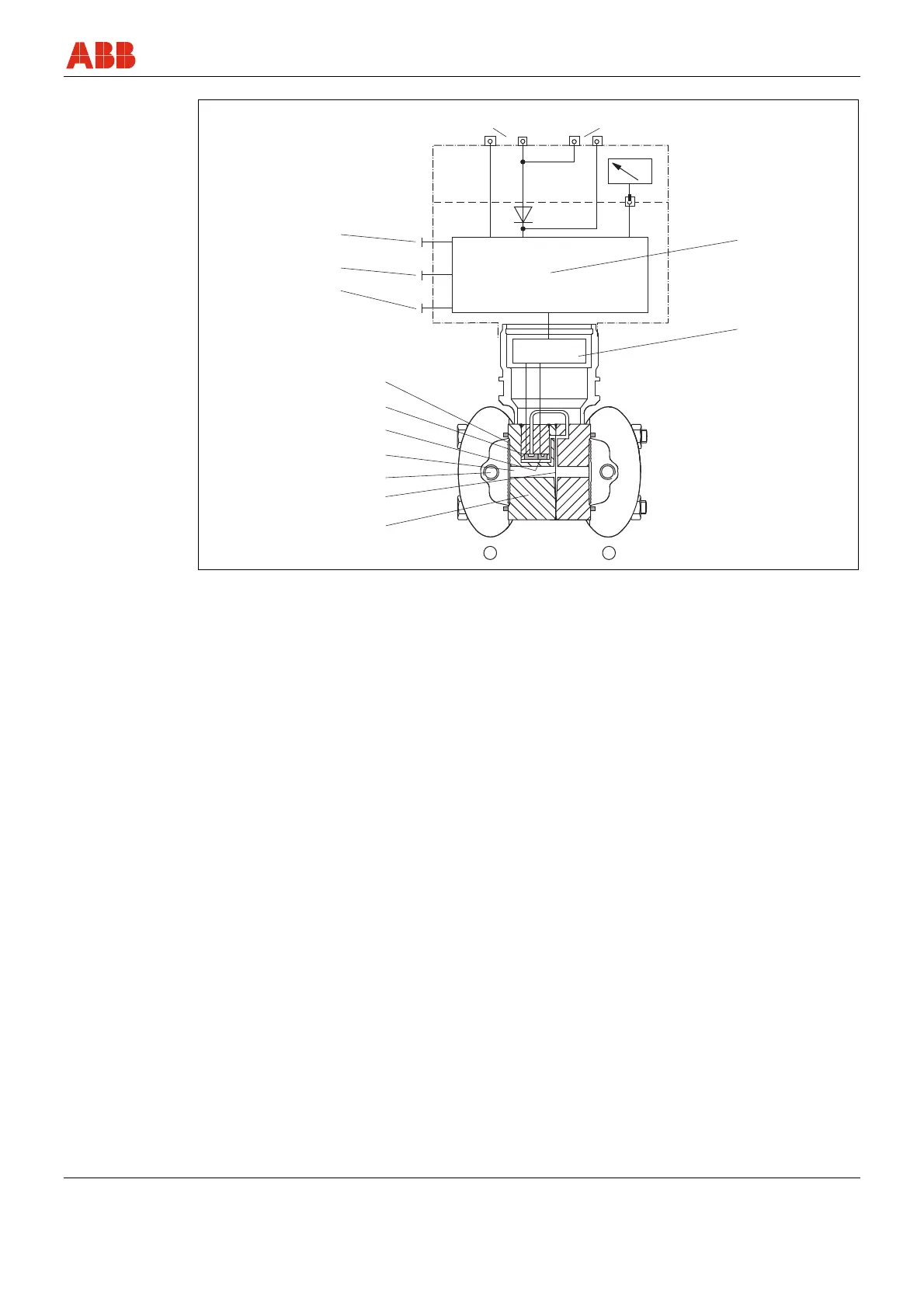
Fig. 4: 265Dx transmitter
1 Measuring cell
2 Overload diaphragm
3 Process connection
4 Filling liquid
5 pabs sensor
6 dp sensor
7 Isolating diaphragm
8 Write protection
9 Span
10 Lower range value
11 Output / power supply
12 Test instrument
13 Microprocessor-based electronics
14 Matching electronics
With HART devices, the 4 … 20 mA output signal can be tested at the "TEST" terminals without
interrupting the signal circuit (this does not apply to fieldbus devices).
Use an ammeter with an internal resistance of < 10 Ω for this purpose. To ensure maximum
possible accuracy, we recommend switching the measuring device directly into the output circuit
for the purpose of configuring or calibrating the transmitter (measuring the current).