1.5.4.2 Device configuration
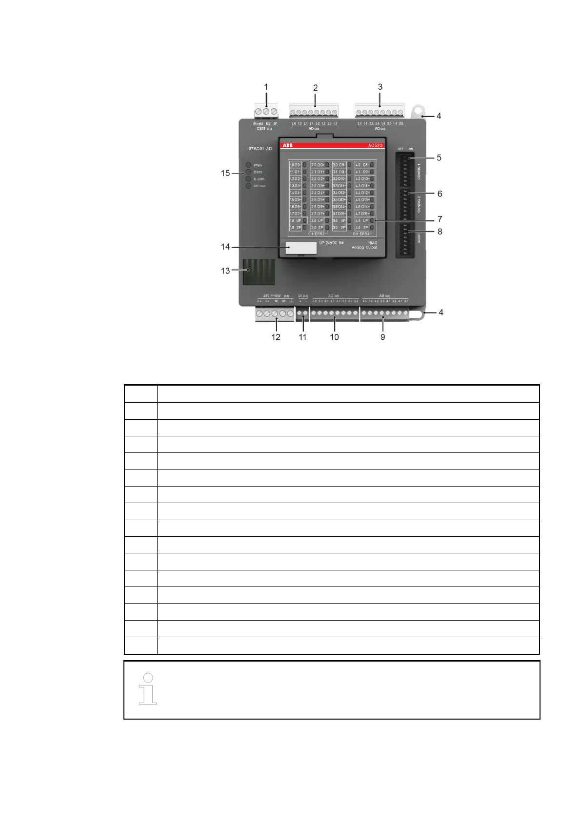
Fig. 67: Front view: 07AC91-AD
No. Description
1 Connection for CS31 bus (X1)
2 Analog outputs (X2): 0 ... 10 V, 0 ... 20 mA
3 Analog outputs (X3): 0 ... 10 V
4 Hole for screw mounting (screw diameter 4 mm, extension torque 1.2 Nm)
5 DIP switch for CONFIG1
6 DIP switch for CONFIG2
7 Status LEDs for AO523
8 DIP switch for ADDR
9 Analog outputs (X7): 0 ... 10 V
10 Analog outputs (X6): 0 ... 10 V, 0 ... 20 mA
11 Enabling input for analog outputs (X5)
12 Supply 24 V DC (incl. AO523)
13 Ventilation
14 TA525: Label
15 4 Status LEDs
When using a control system (PLC/central unit) that is configured via the Auto-
mation Builder software (e.g. 07KT98-ARC-AD), the connection element
ANAI4_20 is no longer available.
Replacement devices: I/O modules > Replacement device 07AC91-AD
2018/09/243ADR010122, 8, en_US108