For further information, please refer to the existing documentation
System description Advant Controller 31.
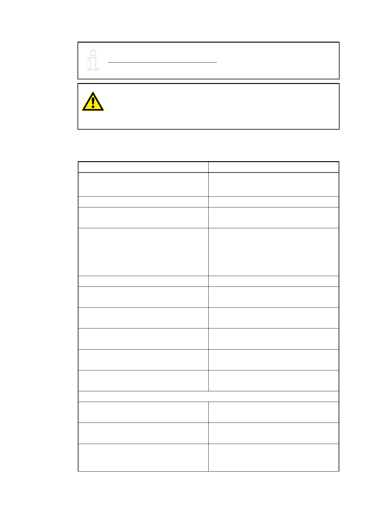
CAUTION!
System damage caused by voltage!
Exceeding the maximum supply or process voltage (>30 V DC) results in per-
manent system damage (destruction).
1.5.1.8.2 Technical Data of the Digital Inputs
Data Value
Connections X2/1.0, X2/1.1, X2/1.2, X2/1.3, X2/1.4, X2/1.5,
X2/1.6, X2/1.7, X3/2.0, X3/2.1, X3/2.2, X3/2.3,
X3/2.4, X3/2.5, X3/2.6, X3/2.7
Input type according to EN 61131-2 Type 1 (realized through current sink)
Input delay: 0 -> 1 or 1 -> 0 *) Replacement device: Typ. 8 ms
Existing device: Typ. 7 ms
Indication of the input signals Replacement device: One yellow LED per
channel. The LED corresponds functionally to
the input signal.
Existing device: One green LED per channel.
The LED corresponds functionally to the input
signal.
Input signal voltage: 24 V DC
-> 0 signal Replacement device: -3 V…+5 V
Existing device: -30 V…+5 V
-> Undefined signal Replacement device: > +5 V…< +15 V
Existing device: > +5 V…< +13 V
-> 1 signal Replacement device: +15 V…+30 V
Existing device: +13 V…+30 V
-> Residual ripple at 0 signal Replacement device: within -3 V…+5 V
Existing device: within -30 V…+5 V
-> Residual ripple at 1 signal Replacement device: within +15 V…+30 V
Existing device: within +13 V…+30 V
Input current per channel:
Input voltage +24 V Replacement device: Typ. 5 mA
Existing device: Typ. 7 mA
Input voltage +5 V Replacement device: > 1 mA
Existing device: ³ 1 mA
Input voltage +15 V Replacement device: > 5 mA
Existing device: ³ 2 mA (at input voltage +13
V)
Replacement devices: I/O modules > Replacement device 07DC91-AD
2018/09/24 3ADR010122, 8, en_US 69