Possible CS31 slaves:
● 07AC91-AD, 07AC91
● 07AC91-AD2
● 07AI91-AD, 07AI91
● 07DC91-AD, 07DC91
● 07DC92-AD, 07DC92
● DC501-CS31-AD, DC501-CS31
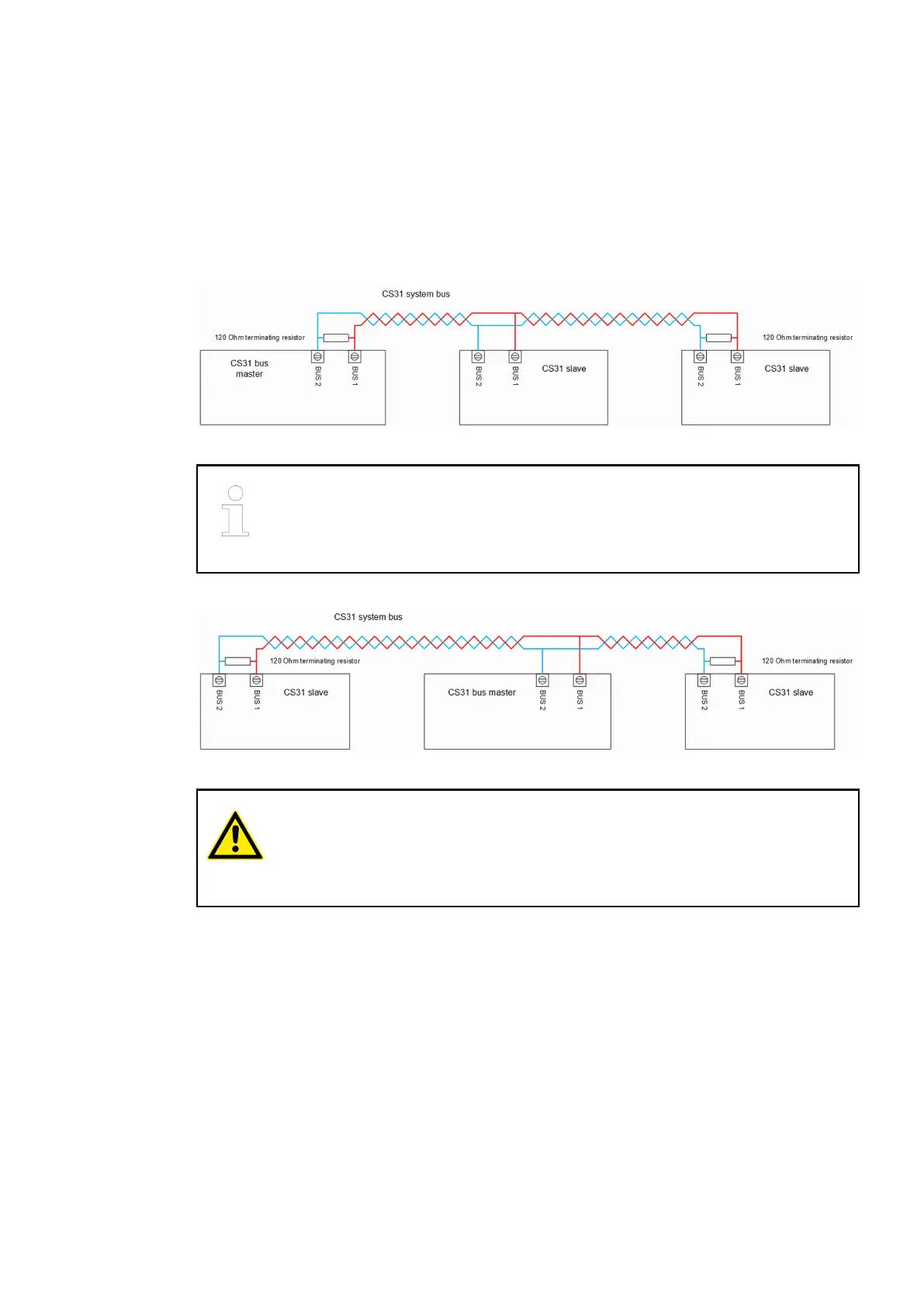
The following diagram shows the bus topology without shielding and earthing treatment:
Fig. 4: Bus topology with CS31 bus master on the side
The CS31 slave DC501-CS31-AD has an internal 120 Ω terminating resistor
which can be connected by using a DIP switch. On the other CS31 slaves and
the CS31 bus master, the terminating resistor must be installed externally by the
user.
The following diagram shows the bus topology without shielding and earthing treatment:
Fig. 5: Bus topology with CS31 bus master in the middle
CAUTION!
Risk of malfunctions!
Spur lines are not allowed within the CS31 bus. Loop the bus line from module
to module.
Correct cable laying:CS31 cable
laying
System data and CS31 bus system data > CS31 bus system data
2018/09/24 3ADR010122, 8, en_US 11