270 Actual signals and parameters
• Starts the speed regulated motor.
• Identifies the next constant speed motor in the rotation.
• Switches the above motor on, but only if the new speed regulated motor had been
running (as a constant speed motor) – This step keeps an equal number of motors
running before and after autochange operation.
• Continues with a normal PFA operation.
Starting order counter
The operation of the starting-order
counter:
• The relay output parameter defi-
nitions (1401…1403 and 1410)
establish the initial motor
sequence. (The lowest parame-
ter number with a value 31
(PFA) identifies the relay con-
nected to 1PFA, the first motor,
and so on.)
• Initially, 1PFA = speed regulated
motor, 2PFA = 1st auxiliary
motor, etc.
• The first autochange operation
shifts the sequence to: 2PFA = speed regulated motor, 3PFA = 1st auxiliary motor,
…, 1PFA = last auxiliary motor.
• The next autochange operation shifts the sequence again, and so on.
• If the autochange operation cannot start a needed motor because all inactive motors
are interlocked, the drive displays an alarm (2015 PFC I LOCK).
• When the ACS320 power supply is switched off, the counter preserves the current
autochange rotation positions in permanent memory. When power is restored, the
autochange rotation starts at the position stored in memory.
• If the PFA relay configuration is changed (or if the PFA enable value is changed), the
rotation is reset. (See the first bullet above.)
Group 81: PFA control
Code Description Range Resolution Default S
No aux 1 aux
motor
2 aux
motors
motors
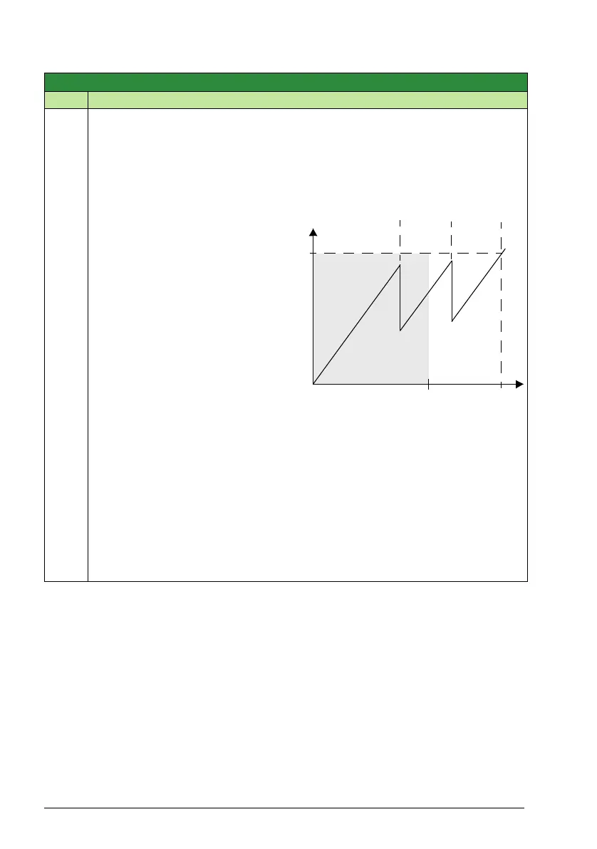
PID output
100%
Output
f
MAX
Area
frequency
autochange
is allowed
8119