Actual signals and parameters 269
8119
AUTOCHNG LEVEL
0.0 … 100.0% 0.1% 50.0%
Sets an upper limit, as a percent of output capacity, for the autochange logic. When the
output from the PID/PFA control block exceeds this limit, the Autochange function is
prevented. For example, use this parameter to deny the Autochange function when the
Pump-Fan system is operating near maximum capacity.
Autochange overview
The purpose of the autochange operation is to equalize duty time between multiple
motors used in a system. At each autochange operation:
• A different motor takes a turn connected to the ACS320 output – the speed regu-
lated motor.
• The starting order of the other motors rotates.
The Autochange function requires:
• External switchgear for changing the drive’s output power connections.
• Parameter 8120 INTERLOCKS = value > 0.
The Autochange function is performed when:
• The running time since the previous autochange operation reaches the time set by
8118 AUTOCHNG INTERV.
• The PFA input is below the level set by this parameter, 8119 AUTOCHNG LEVEL.
Note: The ACS320 always coasts to stop when autochange operation is performed.
In an autochange operation, the Autochange function does all of the following (see the
figure below):
• Initiates a change when the
running time, since the last
autochange operation,
reaches 8118 AUTOCHNG
INTERV, and PFA input is
below limit 8119
AUTOCHNG LEVEL.
• Stops the speed regulated
motor.
• Switches off the contactor
of the speed regulated
motor.
• Increments the starting
order counter, to change
the starting order for the
motors.
• Identifies the next motor in
line to be the speed regulated motor.
• Switches off the above motor’s contactor, if the motor was running. Any other run-
ning motors are not interrupted.
• Switches on the contactor of the new speed regulated motor. The autochange
switchgear connects this motor to the ACS320 power output.
• Delays motor start for the time 8122 PFA START DELAY.
Group 81: PFA control
Code Description Range Resolution Default S
t
B
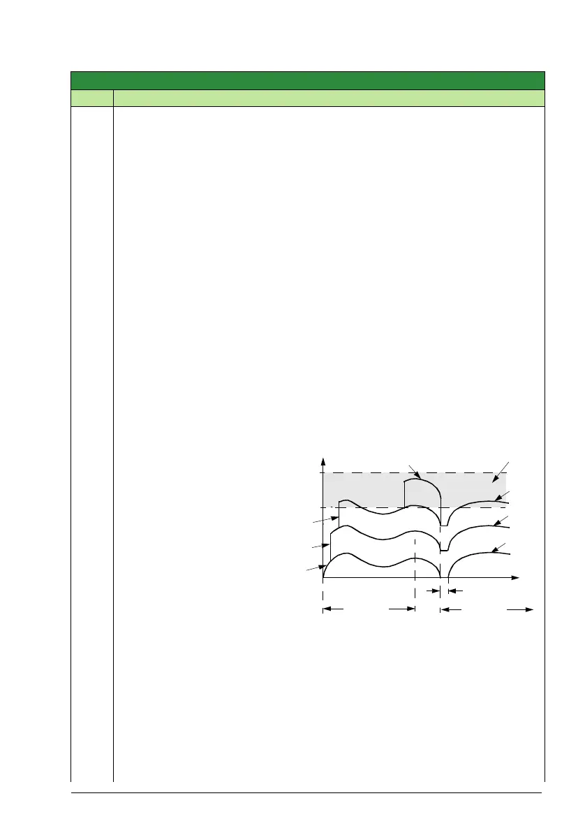
PID Output
100%
1PFA
2PFA
3PFA
4PFA
4PFA
2PFA
3PFA
A
A = Area above 8119 AUTOCHNG LEVEL – autochange
operation not allowed.
B = Autochange operation occurs.
1PFA, etc. = PID output associated with each motor.
8118
8118
8122
8119