110 Control macros
Terminal sizes:
• (frames R0…R8: 0.14…1.5 mm
2
(all terminals)
• Tightening torques: 0.5…0.6 N·m (0.4 lbf·ft)
Notes:
1)
AI1 is used as a speed reference if vector control is selected.
2)
In scalar control (default): See Menu - Primary settings - Start, stop, reference - Constant
frequencies or parameter group 28 Frequency reference chain.
In vector control
: See Menu - Primary settings - Start, stop, reference - Constant speeds
or parameter group 22 Speed reference selection.
3)
Ground the outer shield of the cable 360 degrees under the grounding clamp on the
grounding shelf for the control cables.
4)
Connected with jumpers at the factory.
5)
Only frames R6…R11 have terminals 40 and 41 for external 24 V AC/DC input.
6)
Select voltage or current for inputs AI1 and AI2 and output AO1 with parameters 12.15, 12.25
and 13.15, respectively.
7)
Total load capacity of the auxiliary voltage output +24V (X2:10) = 6.0 W (250 mA /24 V). User
can use this source for either of the I/O connections (DI1... DI2- RO1 or DI3...DI6 - RO2~RO3).
8)
Input signal
9)
Output signal
Input signals
• Analog speed/frequency reference (AI1)
• Start, pulse (DI1)
• Stop, pulse (DI2)
• Direction selection (DI3)
• Constant speed/frequency selection (DI4, DI5)
Output signals
• Analog output AO1: Output frequency
• Analog output AO2: Motor current
• Relay output 1: Ready run
• Relay output 2: Running
• Relay output 3: Fault (-1)
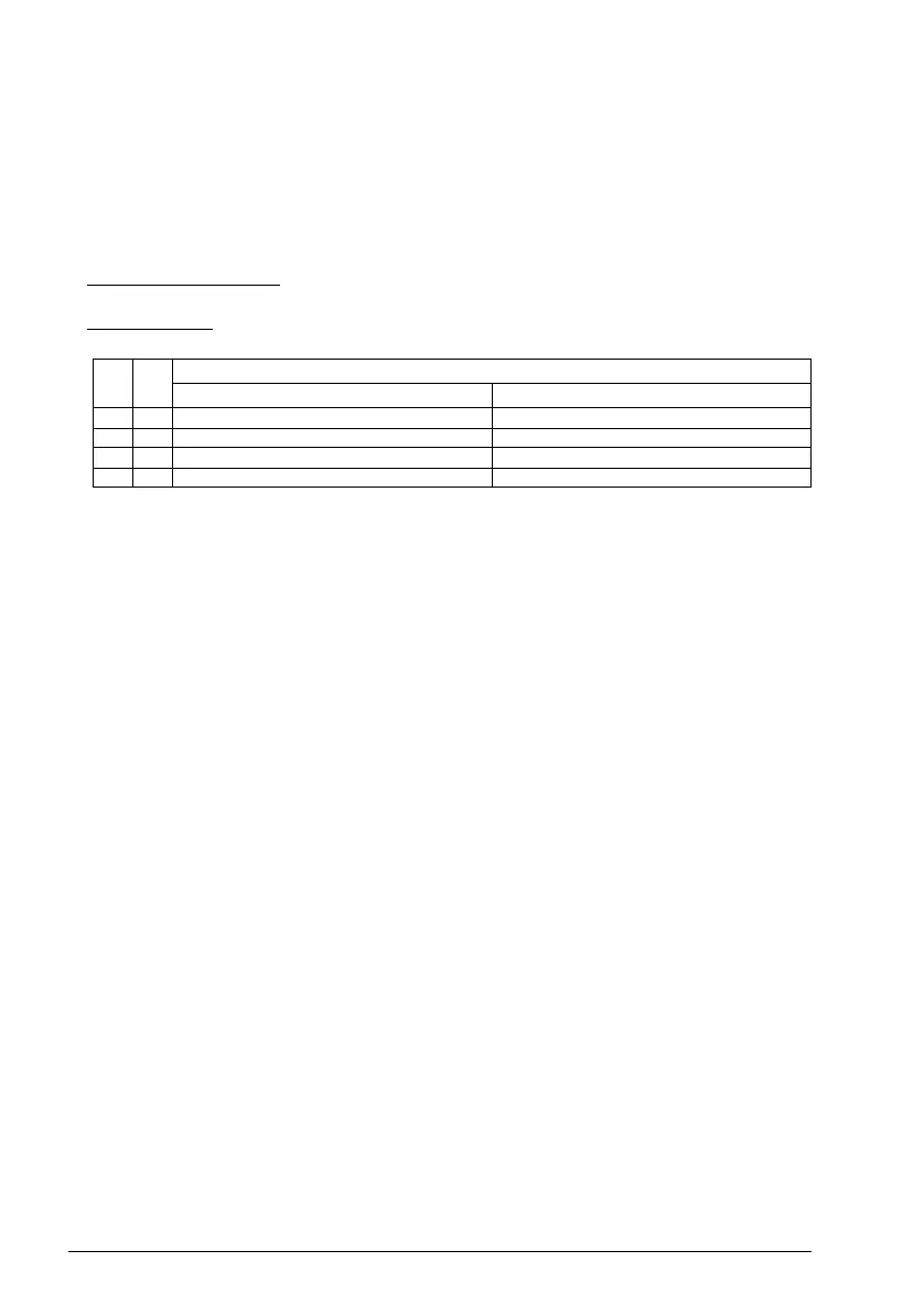
DI4 DI5 Operation/Parameter
Scalar control (default) Vector control
0 0 Set frequency through AI1 Set speed through AI1
1028.26 Constant frequency 1 22.26 Constant speed 1
0128.27 Constant frequency 2 22.27 Constant speed 2
1128.28 Constant frequency 3 22.28 Constant speed 3