Control macros 145
Terminal sizes
• (frames R0…R8): 0.14…1.5 mm
2
(all terminals)
• Tightening torques: 0.5…0.6 N·m (0.4 lbf·ft)
Notes
1)
Current [0(4)…20 mA, R
in
< 500 ohm] or voltage [ 0(2)…10 V, R
in
> 200 kohm]
input as selected with parameter 12.15 AI1 unit selection.
2)
Current [0(4)…20 mA, R
in
= 100 ohm] or voltage [ 0(2)…10 V, R
in
> 200 kohm]
input as selected with parameter 12.25 AI2 unit selection.
3)
Total load capacity of the auxiliary voltage output +24V (X2:10) = 6.0 W (250 mA /
24 V). User can use this source for either of the I/O connections (DI1... DI2- RO1 or
DI3...DI6 - RO2
~RO3).
4)
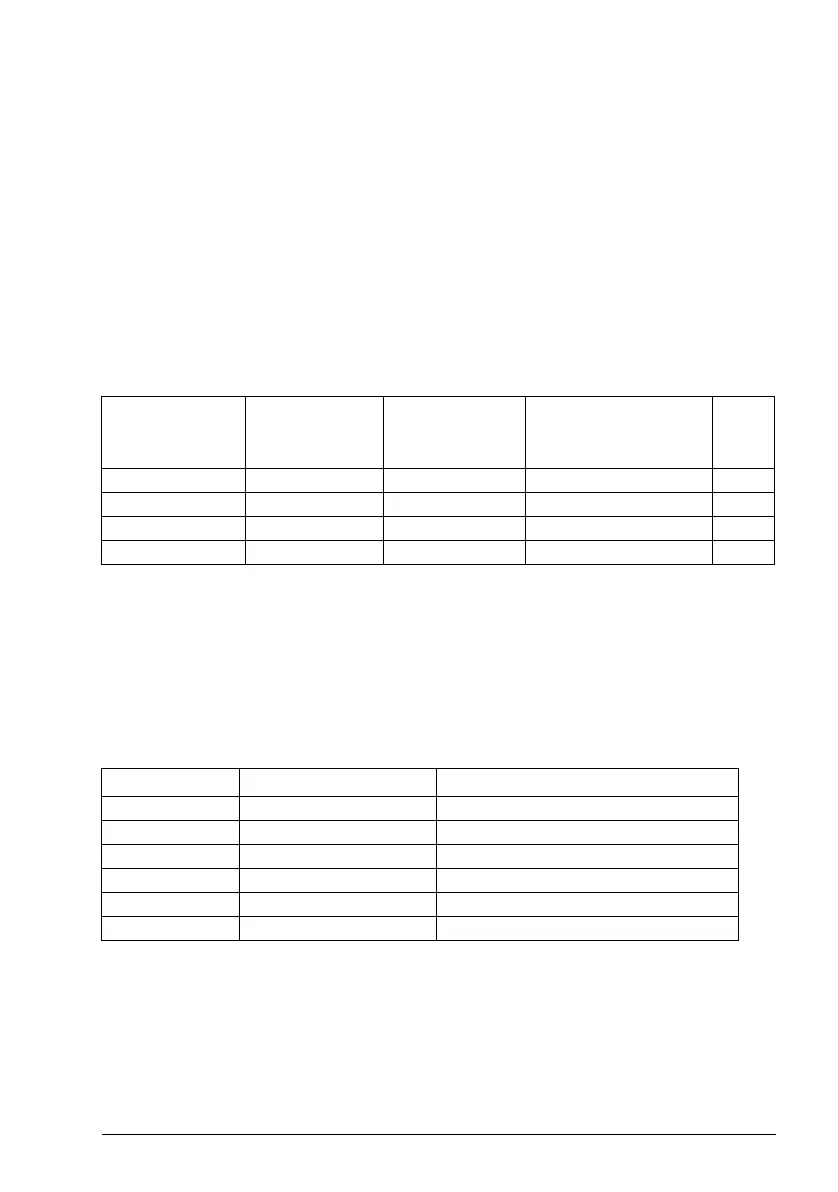
The constant speed is set based on the following combination of sources:
5)
Connected with jumpers at the factory.
6)
Ground the outer shield of the cable 360 degrees under the grounding clamp on
the grounding shelf for the control cables.
7)
Input signal
8)
Output signal
9)
For R0...R2 frames only
In addition, some inputs and settings are set automatically as follows:
For information on cable connection and drive operation, see Control Connections in
the Hardware manual (3AXD50000044998).
Source defined
by No.22.22
Source
defined by
No.22.23
Source defined
by par.22.24
Constant speed
active
Value
0 0 0 Set speed through AI1 -
100 Constant speed 1 600
010 Constant speed 2 900
001 Constant speed 4 1480
No. Name (Input/Setting) Value
20.01 Ext1 commands 4 = In1P Start; In2 Stop
21.03 Stop mode 1 = Ramp
23.11 Ramp set selection 0 = Acc/Dec time 1
23.12 Acceleration time 1 300 s
23.13 Deceleration time 1 300 s
99.04 Motor control mode 1 = Vector