Program features 63
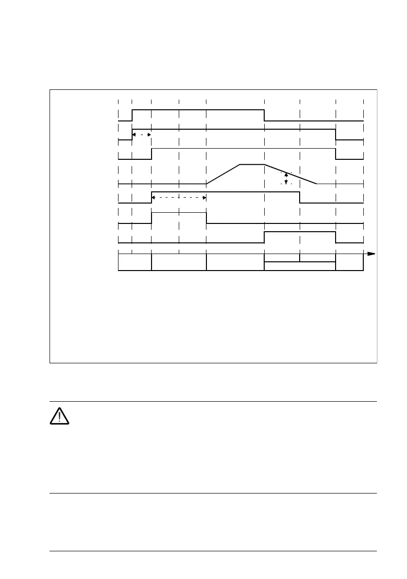
Timing diagram
The simplified timing diagram below illustrates the operation of the brake control
function. Refer to the state diagram above.Wiring example
The figure below shows a brake control wiring example. The brake control hardware
and wiring is to be sourced and installed by the customer.
WARNING! Make sure that the machinery into which the drive with brake
control function is integrated fulfills the personnel safety regulations. Note that
the frequency converter (a Complete Drive Module or a Basic Drive Module, as
defined in IEC/EN 61800-2), is not considered as a safety device mentioned in the
European Machinery Directive and related harmonized standards. Thus, the
personnel safety of the complete machinery must not be based on a specific
frequency converter feature (such as the brake control function), but it has to be
implemented as defined in the application specific regulations.
t
md
Motor magnetization delay
t
od
Brake open delay (parameter 44.08 Brake open delay)
n
cs
Brake close speed (parameter 44.14 Brake close level)
t
cd
Brake close delay (parameter 44.13 Brake close delay)
BCW BRAKE CLOSING WAIT
BCD BRAKE CLOSING DELAY
Start command
(06.16 b5)
Modulating (06.16 b6)
1 23 4 5 6 7 8
Ready ref (06.11 b2)
Speed reference
Brake control signal
(44.01 b0)
Ramp to stopped
request (44.01 b3)
Hold stopped request
(44.01 b2)
t
od
n
cs
BRAKE
CLOSED
State
BRAKE
CLOSED
BRAKE OPENBRAKE OPENING
BRAKE CLOSING
BCW BCD
t
md