Operation principle and hardware description 35
Supply module (frame D8T)
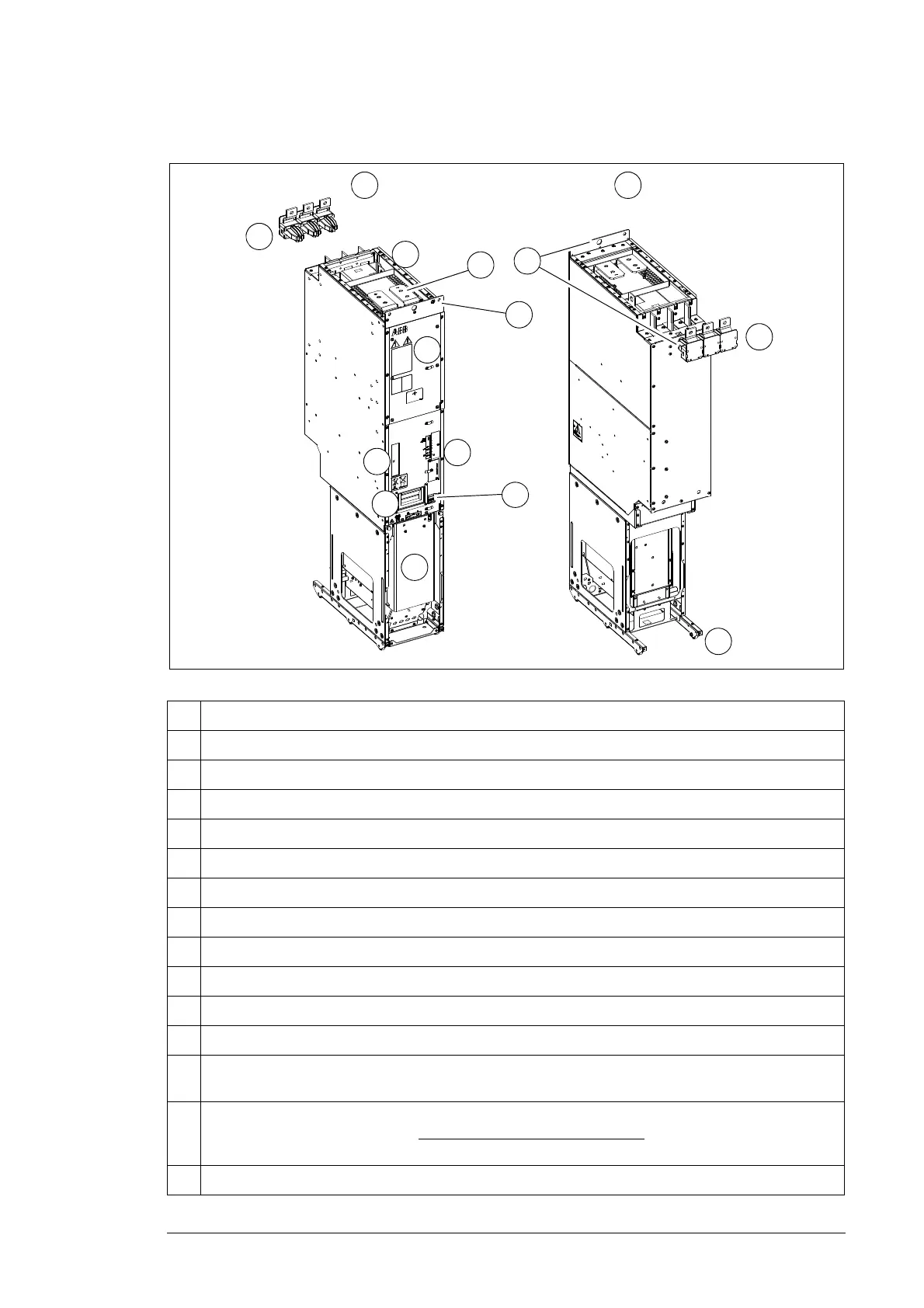
Description
A DSU module, frame size D8T, front
B DSU module, frame size D8T, back
1. DC output busbars
2. Cover panel of the module’s DC fuses
3. Handle
4. Terminal block [X53]. 24 V DC power for supply module control unit.
5. Cooling fan (standard speed-controlled fan shown; a direct-on-line fan is available as option +C188)
6. Quick connector (AC input) (The counterpart fastened to the cabinet behind the module.)
7. Wheels
8. Unpainted fastening hole. The grounding point (PE) between module frame and cabinet frame.
9. Type designation label of the module
10. Terminal block [X50] (power supply for internal boards and module heating element, option +C183;
DOL fan supply, option +C188)
11. Fiber optic connectors (see section Module fiber optic connectors on page 137). Communication link
to the supply module control unit. When speed-controlled fan is in use:
Communication link to fan
control unit.
12. Lifting eyes

 Loading...


