ControlMaster CM10, CM30 and CM50
Universal process controllers,
1
/8,
1
/4 and
1
/2 DIN 4 Installation
16 IM/CM/S–EN Rev. R
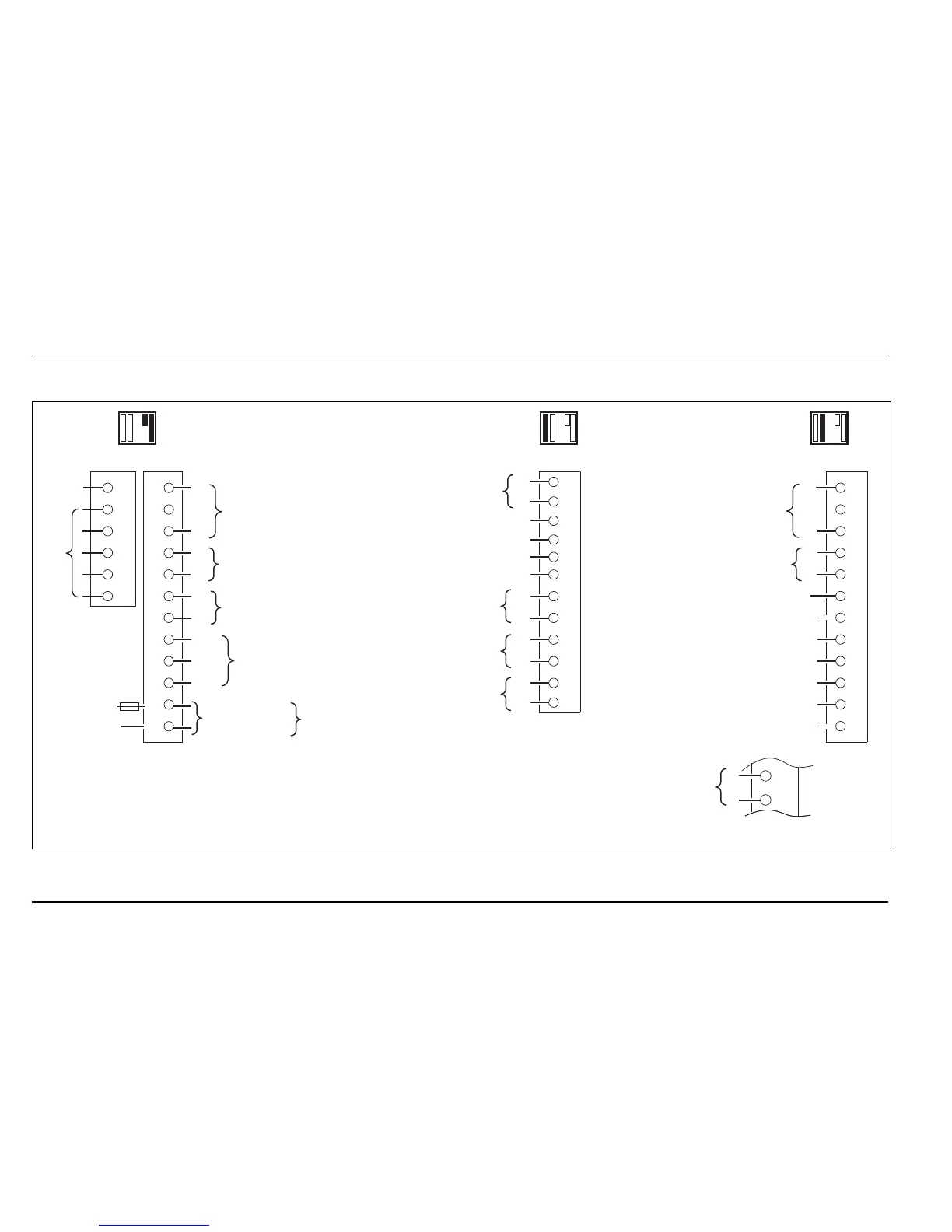
4.5.2 CM30 Electrical Connections
Fig. 4.8 ControlMaster CM30 Electrical Connections
Rear
View
Analog Input 3
Analog Input 4
Tx PSU
Digital Output + External
Digital Input / Output 1
Digital Input / Output 4
Digital Input / Output 5
Digital Input / Output 6
Digital Input / Output –
Comms*
Tx
PSU
Analog Output 2
Rear
View
Option Board 1 Option Board 2Standard Connections
Digital Input / Output 2
Digital Input / Output –
**
C
**
C
**
C
Relay Output 2
Relay Output 3
Relay Output 4
Digital Output + External
Digital Input / Output 3
Analog
Input 1
Analog Input 2
Relay Output 1
Neutral
Line***
100 to
240 V AC
10 W
10 to
36 V DC
NC
C
NO
Analog / Digital
Output 1****
Rear
View
* Refer to rear panel for MODBUS connections
** N/O (factory default) or N/C contact selection made via internal jumper links – see page 12
*** 200 mA Type T fuse (mains AC) or 2 A Type T fuse (120 V DC max.) and external
isolating switch. For UL-marked controllers the fuse must be UL recognized
**** Provides 24 V digital output (observe + and – connections)
**
C
Relay
Output 2
Option Board 1a