ControlMaster CM10, CM30 and CM50
Universal process controllers,
1
/8,
1
/4 and
1
/2 DIN Appendix A – Digital and Analog Sources
116 IM/CM/S–EN Rev. R
Appendix A – Digital and Analog Sources
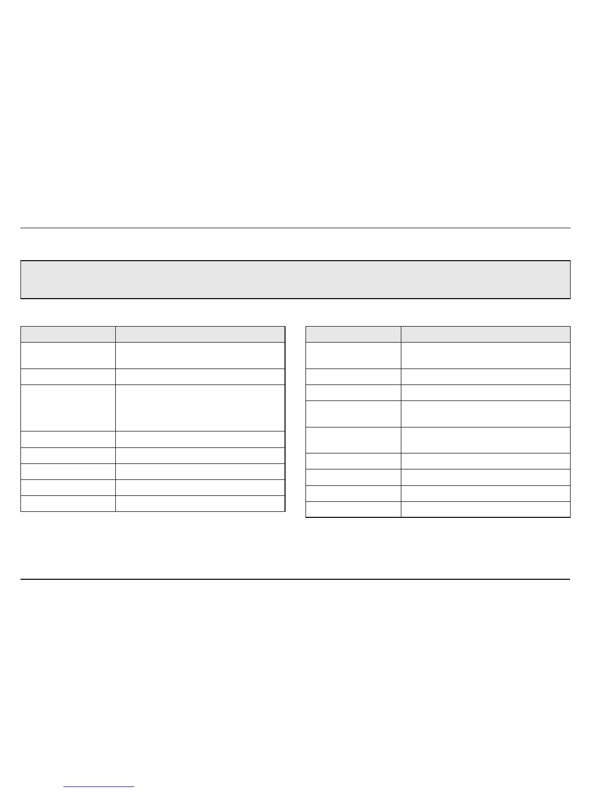
A.1 Digital Sources
Note. Numbers in brackets indicate additional parameters, for example, 'Alarm 1 (8) Ack. State indicates that 8 Alarm Ack.
State parameters are available.
Source Name Description [Comment]
Alarm 1 (8) Ack. State
Acknowledged alarm = 0
Unacknowledged alarm = 1
Alarm 1 (8) State Alarm State
Anlg IP 1 (4) Fail
Analog input failure (active when the signal
detected at the analog input is outside the
fault detect level specified during
configuration).
AO1 (2) Loop Break Analog output
Delay Timer 1 (2) Delay timer state
IP 1 (4) Digital State Input 1 (4) digital state
Linearizer 1 (2) Fail Custom linearizer failure
Logic Equation 1 (8) Logic equation result
Loop 1 SP Mode
Setpoint mode selected
0 = Local, 1 = Remote
Loop 1 Auto Mode Automatic control mode
Loop 1 Close Relay Motorized valve close relay state
Loop 1 LSP 1 (4) State
Local setpoint state
1 = setpoint selected
Loop 1 Manual Mode
Manual control mode
1 = manual
Loop 1 Open Relay Motorized valve open relay state
Loop 1 TP OP1 Time proportioning output
Loop 1 Valve State Motorized valve state
Loop 1 Valve Stuck Motorized valve stuck state
Source Name Description [Comment]