Process connections (option)
The system can handle the following input and output signals from the peripheral
equipment:
• Digital I/O
- up to 96 inputs and 96 outputs
Requires 1-6 digital I/O boards (option)
• Analogue I/O
- up to 4 inputs and 4 outputs
Requires 1 analogue I/O board (option)
• Combi I/O
- 16 digital in- and 16 outputs + 2 analogue outputs
Requires 1 AD combi I/O board (option)
• Computer communication via RS 232 interface.
Requires "Computer link" (option).
• I/O remote bus for Allen Bradly 1771 RIO link, up to 128 in / 128 out (option)
• Control signals for 1-6 external axes.
Requires one extra board (option).
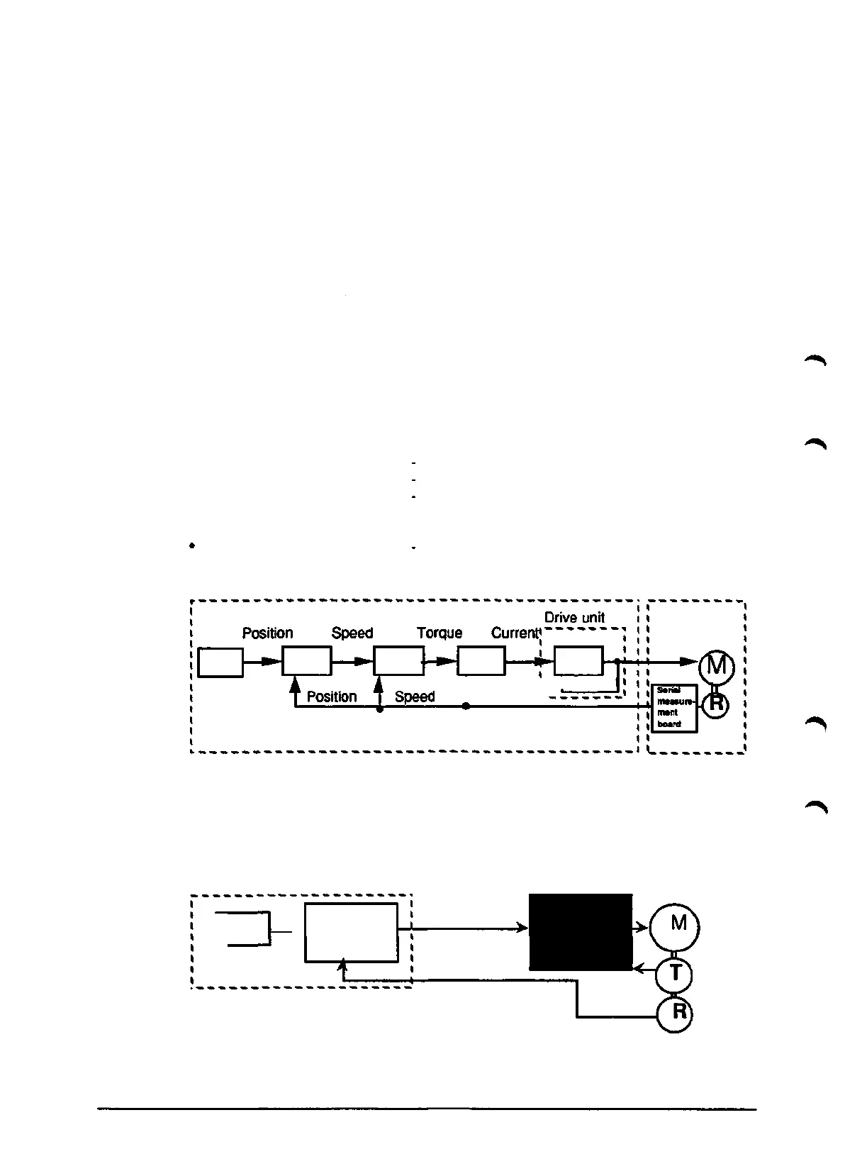
Drive system
The drive system, for the robot motors and one integrated axis 7 (option), consists
of the following units.
• Computer board
• Rectifier unit
• Drive unit
Serial measument board
Control system
for overall control.
for power supply to the drive units.
receives current references from the computer
board. The current references control the
power amplifier supplying current to the motor.
reads the resolver
Manipulator
A » A Curren
TRotor angle-
Fig. 3.5 AC drive system, robot axes and integrated axis 7.
Drive unit for optional external axes is located outside the control system.
Thesedrive units are provided with speed referense by the control system.
Control cabinet
Separate drive unit
outside control system
t
'osition >.
Control board,
external axes
Speed
Position
Fig. 3.6 Drive system external axis.
Description
1KB 2000
12