MANUAL RELEASE OF BRAKES
Every axis of the robot has holding brakes. When positions of the robot axes are changed
with the robot not connected to the control cabinet, an external 24 V DC power supply
must be connected so that the robot brakes can be released. The power supply should
preferably go to the connector in the base of the robot, see figure below.
Axel 6 (P)
c
OV 814
»24V B16 _g
8
TCL
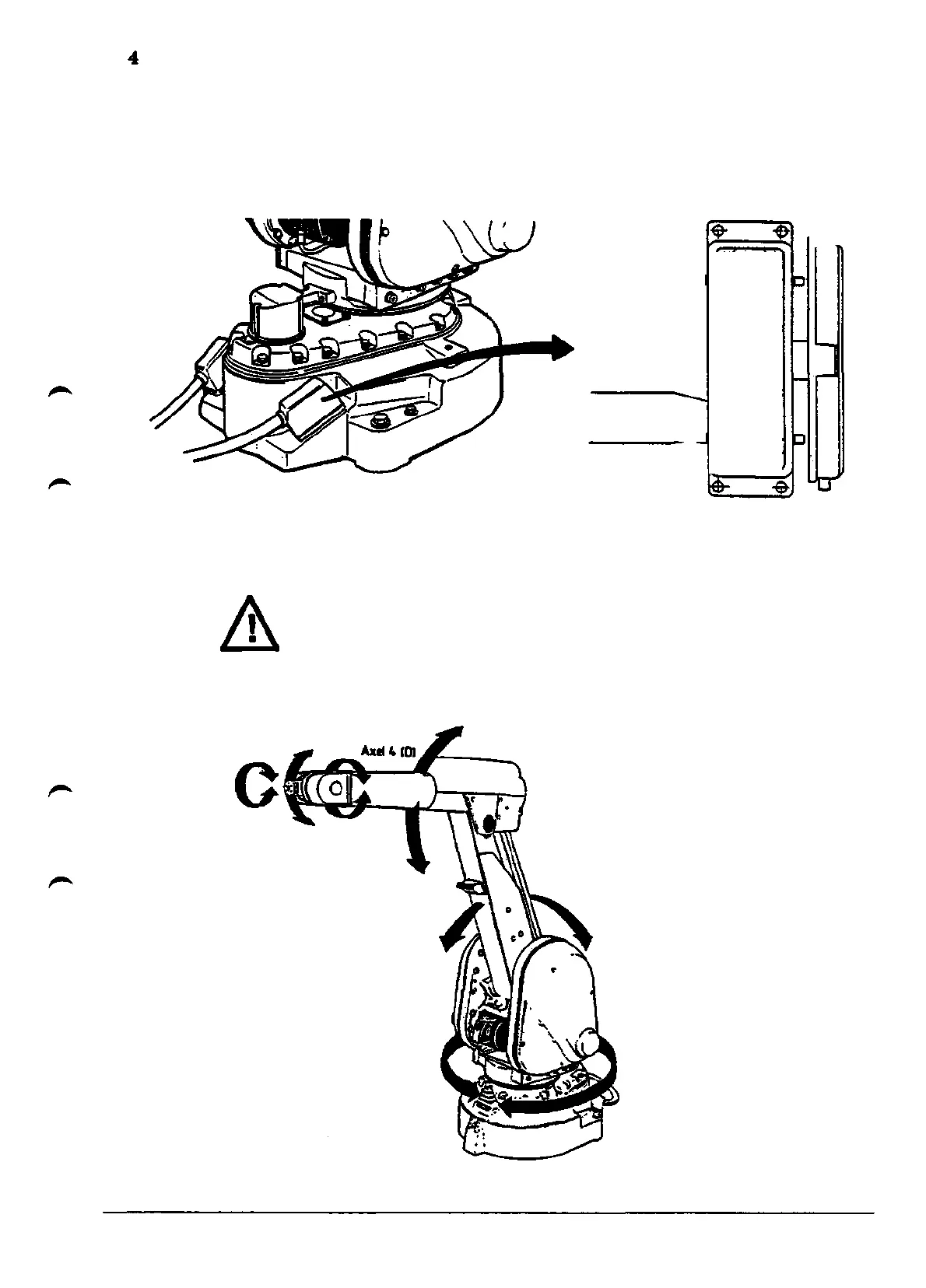
When the control system or the power supply mentioned above is connected, the robot
axes can be released individually by pressing the corresponding button on the gearbox of
axis 3. The buttons are marked with the relevant axis number. The illustration below
shows the locations of the brake release button, the axis designations and motions.
WARNING! Be careful when releasing the brakes! The axes can very rapidly
start moving, thus causing damage or injury!
AttiStE)
Axel 3 (A)
Axel 2 (B)
Axel 1(0
Installation
IRB2000
11