6. SPECIFICATION OF THE ROBOT
The options are described below using the same headings as the ones in the
specification form.
6.1 Manipulator
40 Application interface (customer connection)
43 Air and signals to upper arm
An integrated air supply system is located within the arms. Connection in the base
and outlet in the moving section of the upper arm.
The signall system is part of the cabling of robot. Connection point at the turning
point of the upper arm, consisting of 3 contacts. See chapter 5.1.4 Signal capacity.
6.2 Control system
130 Connection of mains supply
The way the main voltage is connected to the control system can be selected from either
permanent installation or with wall terminals on the left side of the cabinet.
131 Cable bushing
Connection is at the mains filter in the control cabinet, the cable being led through a screw
cap in the wall 11-12 mm. diameter.
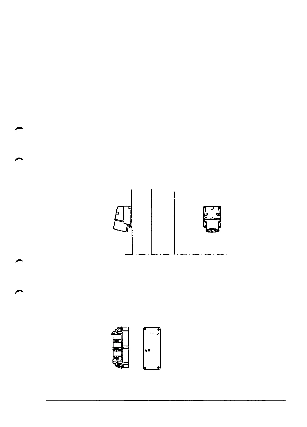
131/132 Connection via wall terminal as per IEC 309-1, -2, CEE 17.
Fig 6.3 Wall inlet.
132 3 x 16 A with protective earth.
133 3 x 32 A with protective earth.
134 Industrial contact unit as per DIN 41640
35 A 600V, 3 phases + earth protection.
Neutral can also be connected to this terminal
[ l
g\
2*
• 3
• 5
6*
M
Fig 6.5 Contact unit
Description
1KB 2000
39