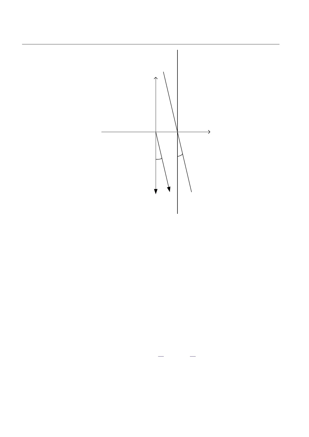
-3U
0
=U
ref
Operate area
Instrument
transformer
angle error
3I
0
(prim)
3I
0
(to prot)
a
Characteristic after
angle compensation
RCAcomp
en06000651.vsd
RCADir = 0º
IEC06000651 V2 EN
Figure 61: Explanation of RCAcomp
Operation mode 3I
0
· 3U
0
· cosφ
Procedure
1. Set the polarizing voltage to 1.2 · UNRel> and the phase angle between
voltage and current to the set characteristic angle (RCADir), the current
lagging the voltage.
2. Measure that the operate power is equal to the SN> setting for the set
directional element.
Note that for operation, both the injected current and voltage must be greater
than the set values INRel> and UNRel> respectively.
The function activates the START and STDIRIN outputs.
3.
Measure with angles j = RCADir +/- 45° that the measuring element operates
when 3I
0
· 3U
0
· cos (RCADir - j) = 3I0 · 3U0 · cos(+/-45) = SN>.
4. Compare the result with the set value. Take the set characteristic into
consideration, see figure
60 and figure 61.
5.
Measure the operate time of the timer by injecting 1.2 · UNRel> and a current
to get two times the set SN> operate value.
Section 13 1MRK 504 088-UEN C
Verifying settings by secondary injection
142
Installation and commissioning manual

 Loading...


