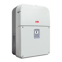
• Install spacers
24
in the two lower
rear attachment pins
27
of the
power module. This will prevent
backwards tilt when the power
module is hung on the bracket.
• Lift the power module up to
the bracket using the (optio-
nal) handles
06
or the (op-
tional) M12 eyebolts, or ano-
ther appropriate lifting device.
The power module is pre-equip-
ped with metal expansions which
allow it to be temporarily put ver-
tically on the oor to make it ea-
sier the installation of handles or
eyebolts.
Risk of injury due to
the heavy weight of
the equipment.
• Insert the heads of two upper
rear attachment pins
27
into
the slots on the bracket and
conrm that the slots on the
bracket are aligned with the line
on the sides of the power modu-
le. This indicates that they have
been correctly positioned.
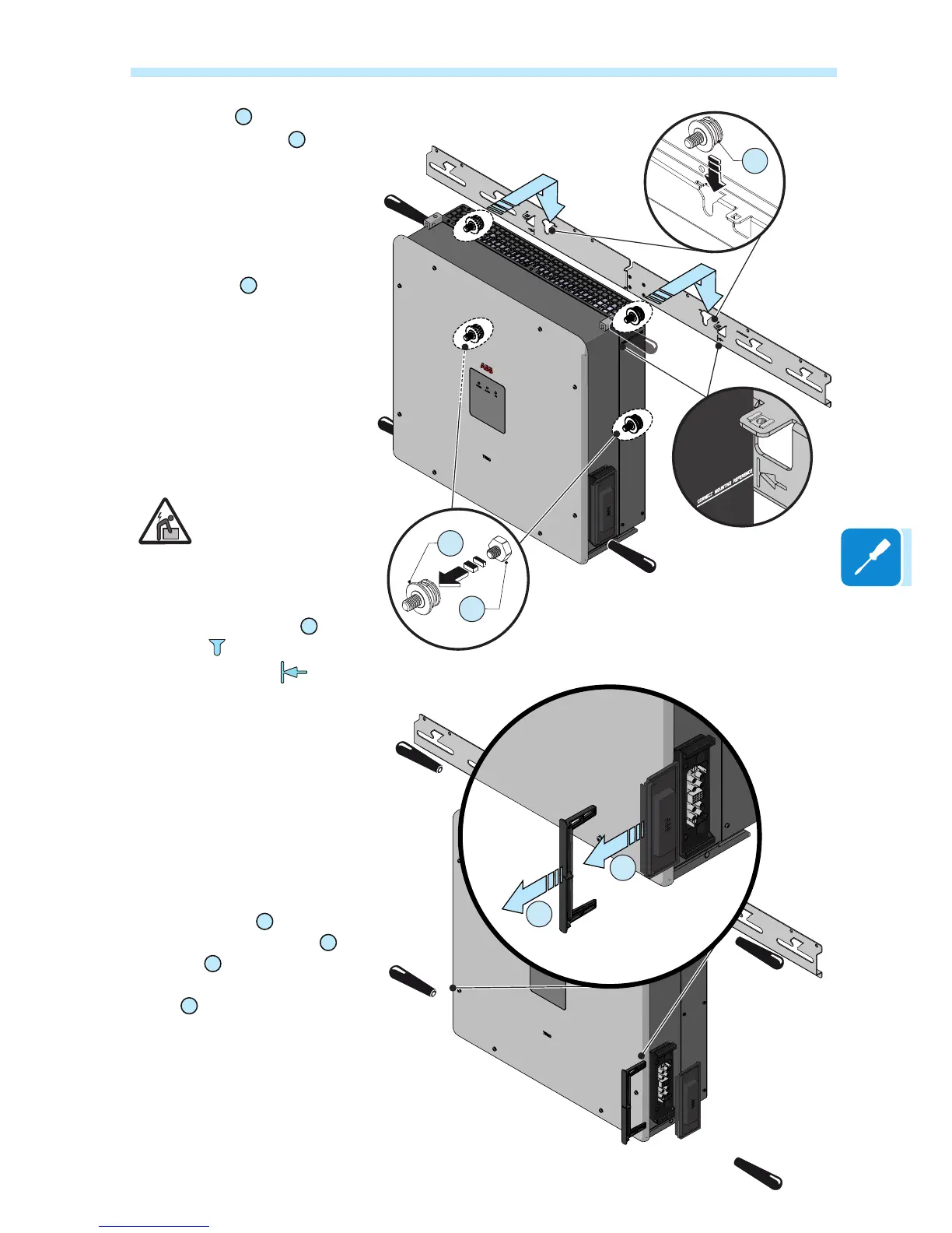
• Remove handle or eye bolts (if
used)
• Remove the quick disconnect
connector covers
04
as follows:
- Pull the metal locking fork
07
outwards
A
- Pull off the quick disconnect
cover
B
Save both parts. They will be
needed in a later step.
27
27
24

 Loading...