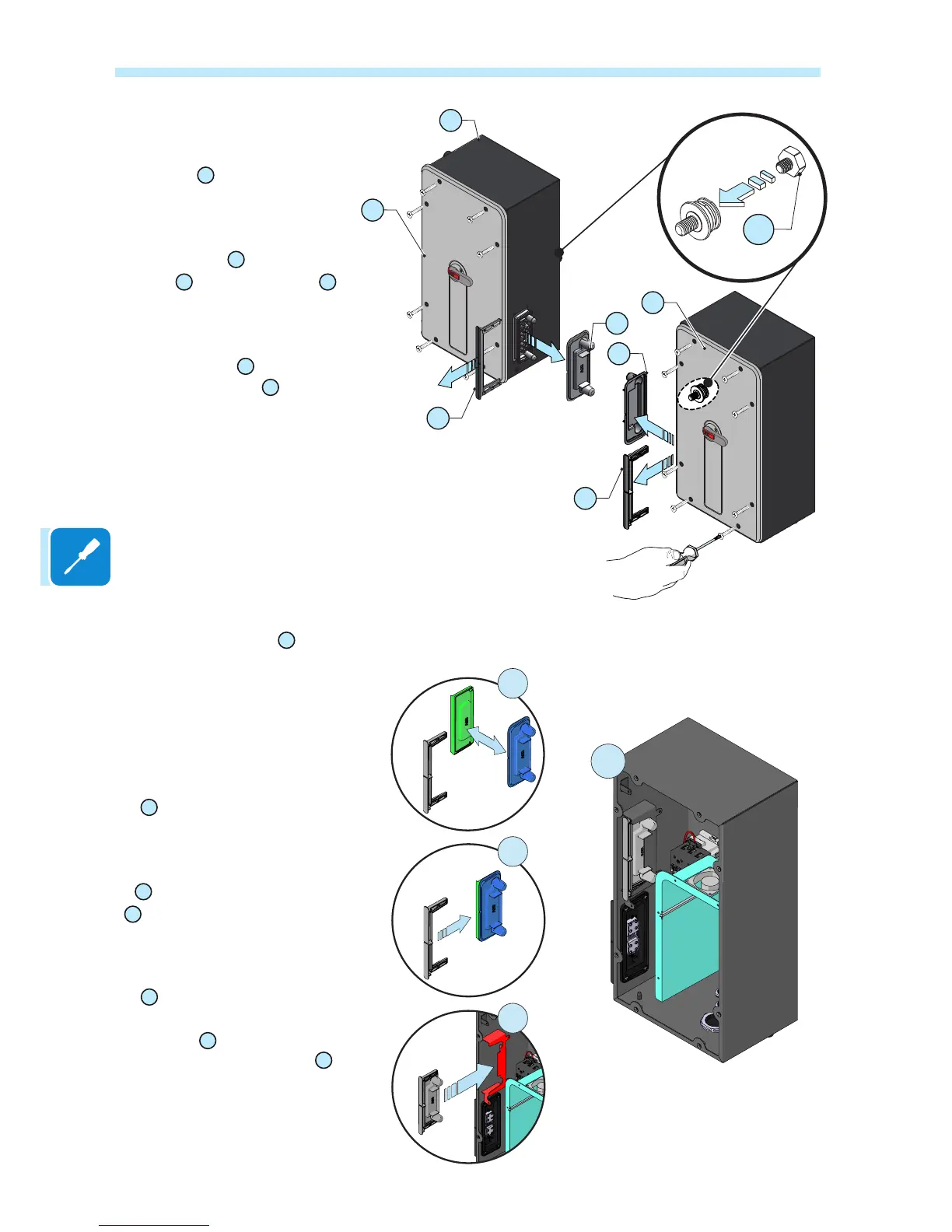
• Set the wiring box disconnect
switches to “0”; otherwise it will
not be possible to remove the
front cover
08
.
• Unscrew the 8 screws holding
the front covers
08
of the DC wir-
ing box
02
and AC wiring box
05
in place. Don’t lose the screws!
• Install 1 spacers
24
in the lower
rear attachment pin
27
of each
wiring box. This will prevent
backwards tilt when the wiring
box is hung on the bracket.
• Remove the covers
04
from
the quick disconnect connec-
tors, one on each wiring box.
Then follow these steps to
store these caps. They will
be needed if the assembly
ever needs to be shipped:
-
A
couple a power modu-
le connector cover (green in
the gure) with one from a wi-
ring box (in blue in the gure).
-
B
Slip the plastic locking fork
38
, which was used to secu-
re the wiring box cover, over
the two covers. Be sure the
fork is plastic, not metal.
-
C
Insert the two connec-
tor covers and plastic lo-
cking fork
41
in the dedicated
space in the wiring box
D
.
- Repeat the same operation for
the other wiring box.

 Loading...