XIO USER MANUAL | 2106424MNAA | 13
—
2 Physical Description
2.1 XIO Housing
A DIN rail mountable plastic housing packages the XIO electronic boards and components.
The XIO must be installed on an interior wall, or in an enclosure that meets
the environmental ratings
for the location. See section 2.1.1 Enclosures for information about ABB
. See section 3.1.1 Enclosure requirements for information about third-party enclosures.
The housing is an interlocked top cover and a base.
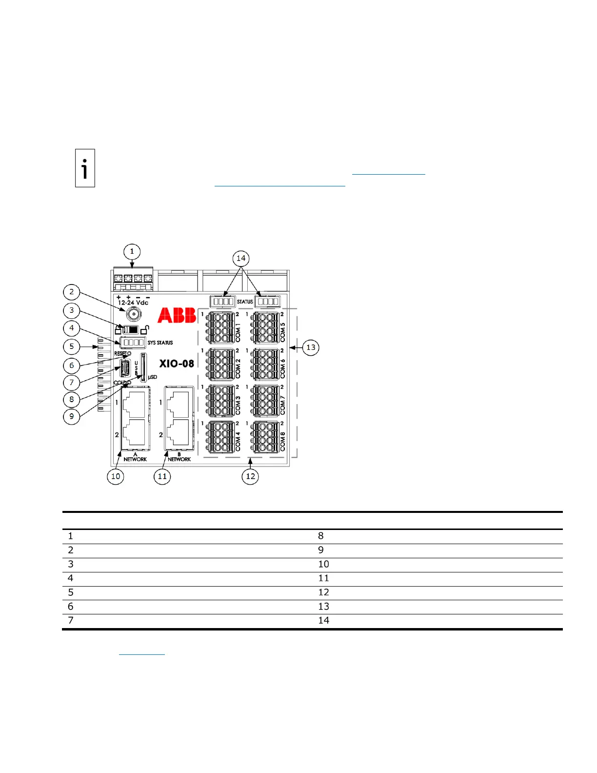
The following figures illustrate the XIO components and interfaces (ports).
Figure 2-1: XIO housing cover
Legend: XIO housing cover
External power supply input (12 or 24 Vdc)
Cold button (paperclip actuated)
A Network Ethernet ports 1 and 2
B Network Ethernet ports 1 and 2
TFIO Module interface (male)
COM 1 – Com 8 Serial communication ports
Reset button (paperclip actuated)
TFIO Module interface (female)
Communication card status LEDs
The electronic boards are inserted into a backplane at the base and the mounting clips are accessible on
the exterior. Figure 2-2 illustrates the exterior of the housing base.