XIO USER MANUAL | 2106424MNAA | 19
name
Data transfer rate (port speed)
2)
10/100 Mbps Full Duplex (supports auto-
negotiation and uses standard or straight-
Ethernet cable)
Realtime data communication between
XIO and RMC.
For additional details on Ethernet connections, refer to section 10 Ethernet
, or click Help on the Networking tab when connected to the device with the
2.2.2 TFIO expansion interfaces
The XIO provides two ports to add modular I/Os. The XIO supports up to 22 TFIO modules.
The XIO uses an independent bus to communicate with the modules. Totalflow has an I/O protocol to
exchange information between the modules and the XIO. The bus operates in a master/slave mode, with
the main board acting as master.
The TFIO modules are DIN rail mountable and employ contact technology for field wiring. The modules
interconnect to each other to provide the necessary power and interface signals along the bus.
The TFIO modules are hot-pluggable and can be inserted, replaced or removed during the normal
operation of the device with no restart required. The system will detect any changes to the modules on
the TFIO bus and the module states can be verified with PCCU.
DANGER – Serious damage to health / risk to life. Explosion Hazard: Do not connect or
disconnect TFIO modules, connectors or their terminations while energized unless the area is
known to be non-hazardous.
Power compatibility for TFIO modules depends on module type:
− Older green modules must only use 12 Vdc.
− M2 modules and newer grey modules can use 24 Vdc.
− A combination of green modules, and M2 modules or grey modules, must only use 12 Vdc.
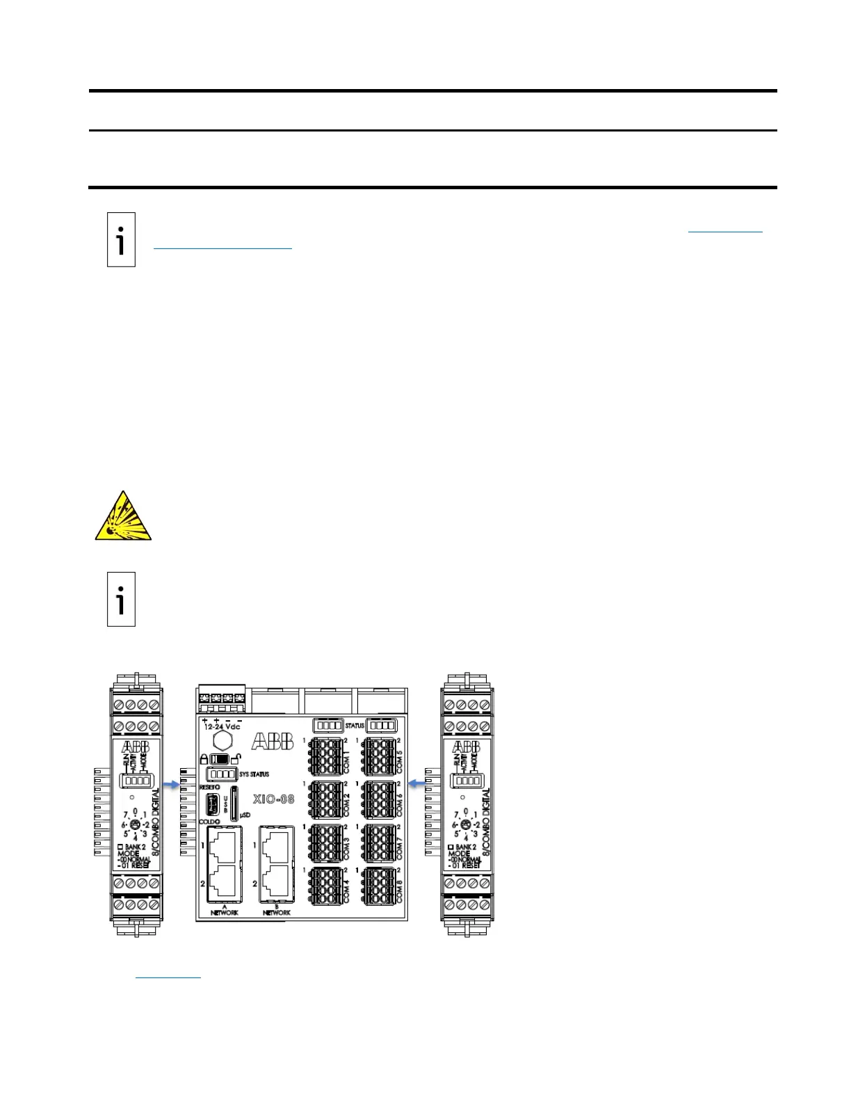
Figure 2-8: TFIO module connections to XIO
All modules have four LED lights, a manual reset button, and a selectable address from zero through
seven (Figure 2-9
). The faceplate of each module shows:
– Type of module