XIO USER MANUAL | 2106424MNAA | 31
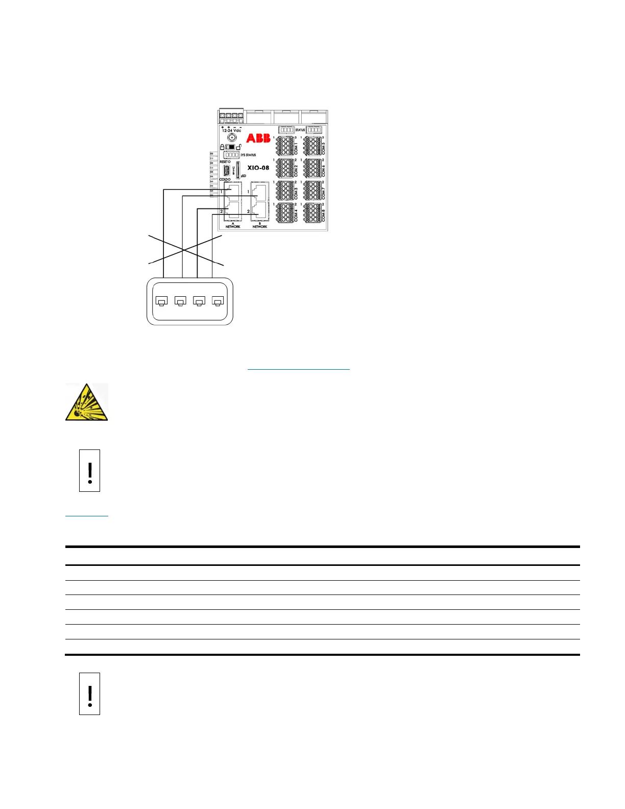
As illustrated in the following drawing, do not connect A1 and A2 or B1 and B2 to the same Ethernet
switch if they are in 1 Network Mode. Connecting both sets of ports to the same switch disables the ports.
Figure 3-5: Wrong Ethernet connection
3.4.5 Connect TFIO modules
TFIO modules connect directly to the TFIO ports on either side of the XIO. For additional information, refer
to the TFIO Module User Manual under Additional information.
– Serious damage to health / risk to life. Do not connect or disconnect TFIO
connectors or their terminations while energized unless the area is known to be non-
– Equipment damage. When the TFIO interface is disabled, the modules remain
powered. Remove the power from the
XIO before connecting or disconnecting additional TFIO
s. Failure to power down the XIO can result in damage to the module. The procedure in this
XIO is powered off.
Table 3-4 identifies the different module types available with the XIO that supports 12 volts to 24 volts
operation. The XIO does not support the TFIO CIM module, part number 2100421.
Table 3-4: TFIO modules
– Equipment damage. The maximum voltage to operate legacy TFIO modules (green
) is 12 Vdc. More than 12 Vdc damages legacy TFIO modules. Only later versions of the
TFIO modules support voltages higher than 12 Vdc
.