106 ZX2 GAS-INSULATED MEDIUM VOLTAGE SWITCHGEAR
—
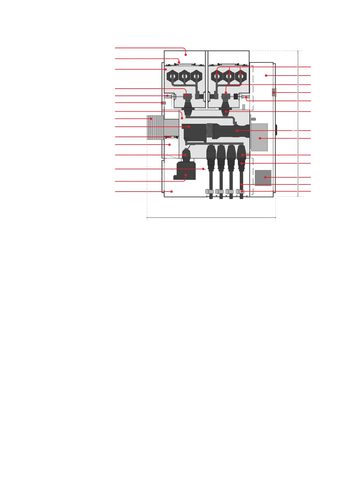
Fig. 11.3
—
Fig. 11.3
Feeder panel 2400 A,
double busbar, example
configuration
1.0 Circuit-breaker compartment
1.1 Circuit-breaker pole
1.2 Circuit-breaker operating mechanism
1.3 Cable socket
1.3b Outer cone
1.4 Test socket
(also for use with other plug-in devices)
1.5 Capacitive voltage indicator system
1.8 Voltage transformer
1.9 Block-type transformer
1.10 Ring core current transformer
1.12 Bushing, circuit-breaker/busbar
compartment
1.13 Pressure relief disk
1.15 Current transformer
1.20 Heat sink
2.0 Busbar compartment
2.1 Busbar system
2.3 Three position disconnect
2.4 Disconnect
2.5 Three-position disconnect mechanism
2.6 Disconnect mechanism
3.0 Cable termination compartment
3.1 Cable connector
3.2 High voltage cable
3.3 Cable fastener
3.5 Main grounding bar
4.0 Plenum, rear
(for circuit-breaker compartment and cable
termination compartment)
4.1 Plenum, top
(for busbar compartment)
6.0 Low voltage compartment
6.1 Central unit of a combined protection and
control device (only for separated versions)
6.2 Human-machine interface of a combined
protection and control
2.0
2.6
2.4
1.5
1.20
1.0
1.15
1.13
4.0
1.4
3.5
1.8
3.0
1.13
4.1
2.1
6.0
2.3
1.12
1.2
1.1
1.3a
3.1
6.1
3.2
3.3
6.2
2.5
90.6 in
86.2 mm