3. INSTALLATION OF THE SWITCHGEAR AT SITE 35
Hazard warning
Operation of the switchgear with open
busbar sockets (including those in the
course of the busbars, e.g. in sectionaliser
—
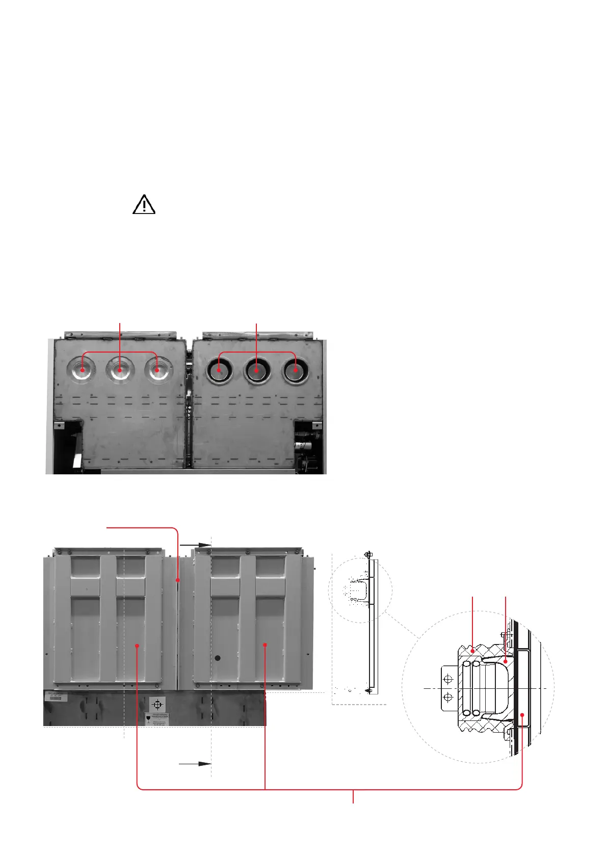
Fig. 3.3.3.1:
Blanking plugs for
busbar sockets
A
A
Section A-A
Busbar socket Blanking plug
Pressure plate
Voltage-proof end insulators
Open busbar sockets
—
Fig. 3.3.3.1
—
Fig. 3.3.3.2
3.3.3. Closure of busbar sockets
Open busbar sockets (e.g. for future extensions
of the system or on coupling panels) must be
fitted with insulating blanking plugs. Pressure
plates are used to fasten the insulating blanking
plugs (Fig. 3.3.3.2) in place. Appropriate pressure
plates must be used depending on the panel
variant. The relevant assembly drawings are part
of the delivery.
—
Fig. 3.3.3.2:
View of the
assembled unit
Gap: 3 mm
• Treat the busbar sockets and the insulating
blanking plugs as described in Chapter 3.1.3.
• Insert the insulating blanking into the busbar
sockets (Fig. 3.3.3.2) and assemble the pressure
plates according to the assembly drawings pro-
vided.
• In the case of double busbar systems, align the
two pressure plates so that a gap of approx.
0.12 in remains between the two pressure plates
(Fig. 3.3.3.2).