86 ZX2 GAS-INSULATED MEDIUM VOLTAGE SWITCHGEAR
Grounding the voltage transformers
To ground the voltage transformers, pull out the
lock knob
3
and turn the operating lever
4
with
a key (see accessories) counter-clockwise as
shown on the direction of rotation indicator
5
.
Release the lock knob. Turn the operating lever
counter-clockwise until the lock knob engages in
the limit position of the isolating device.
Important note
When the lock knob engages in the limit
position, the dielectric strength of the
isolating device is ensured.
Close flap
2
and secure the isolating device with
a padlock.
Connecting the voltage transformers
To connect the voltage transformers, pull out the
lock knob
3
and turn the operating lever
4
with
a key (see accessories) clockwise as shown on the
direction of rotation indicator
5
. Release the
lock knob. Turn the operating lever clockwise
until the lock knob engages in the limit position
of the isolating device.
Important note
When the lock knob engages in the limit
position, the current carrying capacity of
the isolating device is ensured.
Close flap
2
and secure the isolating device with
a padlock.
5.8.1. Operation of the isolating device for
voltage transformers in metering panels
Hazard warning
Isolate the relevant switchgear section
before connecting or disconnecting
voltage transformers.
• Comply with the safety regulations to
• Check the switchgear section for the
off-circuit condition as described in
section 5.1.
• Ground the switchgear section and
secure the working area in accordance
• Switch the mcbs (
1
operating mechanisms off in order to
prevent the switchgear section being
energized by remote control.
The device for isolation of the voltage
transformers (fig. 5.8.1.1) for measurement of the
front busbar is located in the low voltage
compartment. Operation of the isolating device
for the voltage transformers on the rear busbar is
effected from the rear of the panel. Operation is
identical in both cases.
The isolating device can be secured with a
padlock. Remove the padlock prior to operation.
Swing flap
2
to the left.
The controls and displays for the voltage
transformer isolating device can be found behind
the flap. Observe warning label
7
. Check the
switch position indicator
6
.
—
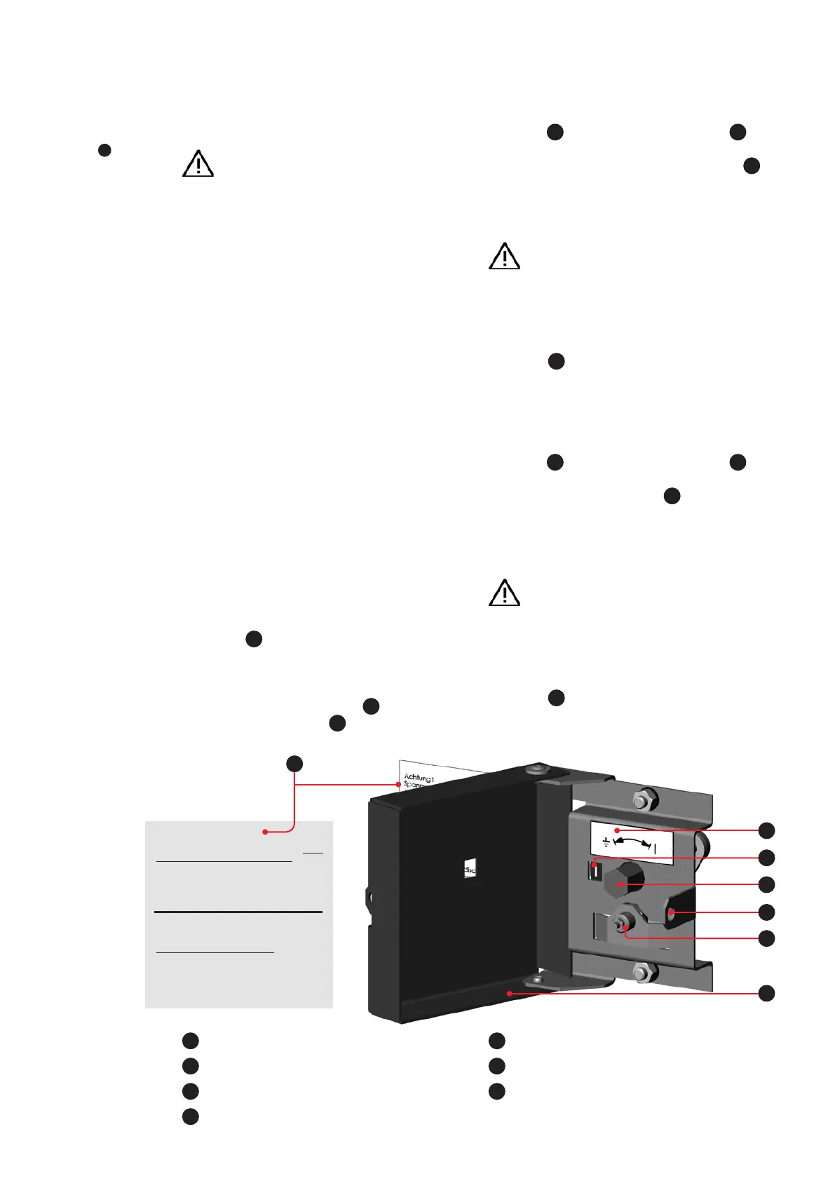
Fig. 5.8.1.1:
Controls and displays
for the voltage trans-
former isolating device
with flap
2
opened
Achtung!
Spannungswandler-Abtrennvorrichtung nur in
Spannungsfreiem Zustand betätigen.
- Schloss entfernen
- Rastknopf ziehen
- Betätigungshebel drehen bis
Rastknopf wieder einrastet
Attention!
Operating of the vt-isolating system
only under no-voltage condition.
- remove the padlock
- pull the lock knob
- rotate the operation lever up to the
stop till the lock knob arrests again.
1
Bar for padlock
2
Flap
3
Lock knob
4
Operating lever (hexagon 17 mm AF)
5
Direction of rotation indicator
6
Switch position indicator
7
Warning sign
7
5
6
1
3
2
4