5. OPERATION 83
5.6.1. Switch position grounding
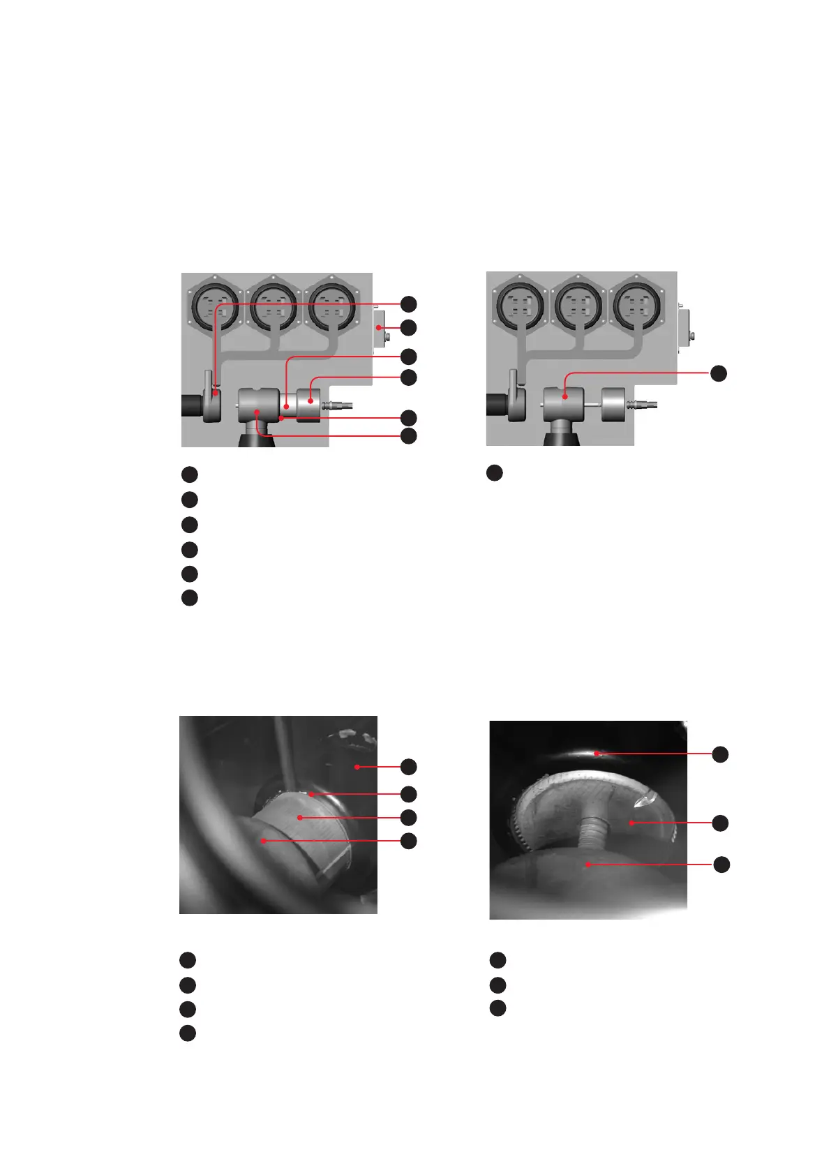
The red mark on the moving contact must be
flush against the face of the central part of the
disconnect switch (moving contact bridges
central part of disconnect switch and grounding
switch contact - fig. 5.6.1.1 and 5.6.1.2).
—
Fig. 5.6.1.1:
Switch position ground-
ing switch CLOSED
—
Fig. 5.6.1.2:
Switch position ground-
ing switch CLOSED
(viewed through
view port)
—
Fig. 5.6.2.1:
Switch position OPEN
—
Fig. 5.6.1.1.
The sliding contact is in the central part of the
disconnect, such that the face surface of the
sliding contact is flush with the face surface of
the central part of the disconnect (central
position of the sliding contact - see fig. 5.6.2.1
and 5.6.2.2).
—
Fig. 5.6.2.2:
Switch position
OPEN (viewed
through view port)
2
1
Disconnect switch contact
2
View port
3
Moving contact
4
Grounding switch contact
5
Slot marked red
6
Central part of disconnect switch
1
3
4
5
6
7
7
Moving contact
(in central part of disconnect switch)
—
Fig. 5.6.2.1.
6
3
5
4
6
3
4
3
Moving contact
4
Grounding switch contact
5
Slot marked red
6
Central part of disconnect switch
3
Moving contact
4
Grounding switch contact
6
Central part of disconnect switch
—
Fig. 5.6.1.2.
—
Fig. 5.6.2.2.