44 ZX2 GAS-INSULATED MEDIUM VOLTAGE SWITCHGEAR
• Deblock the locking knobs (3.3.7.1.3) for the
three phases one after another (= slide them to
the right). The locking plates are pressed out-
wards by approx. 0.8 in in that process.
• First install the two outer voltage transformers
and then the middle voltage transformer as de-
scribed below.
• Remove the protective caps from the silicone
parts of the voltage transformers and store
them for further use.
Important note
Check the silicone part of the voltage
transformer for damage. Observe the
notes in section 3.1.3.
Clean and grease the silicone insulating
part of the voltage transformer as
described in section 3.1.3.
• Remove the dust protection cap or blanking
plug from the voltage transformer socket and
store the components for further use.
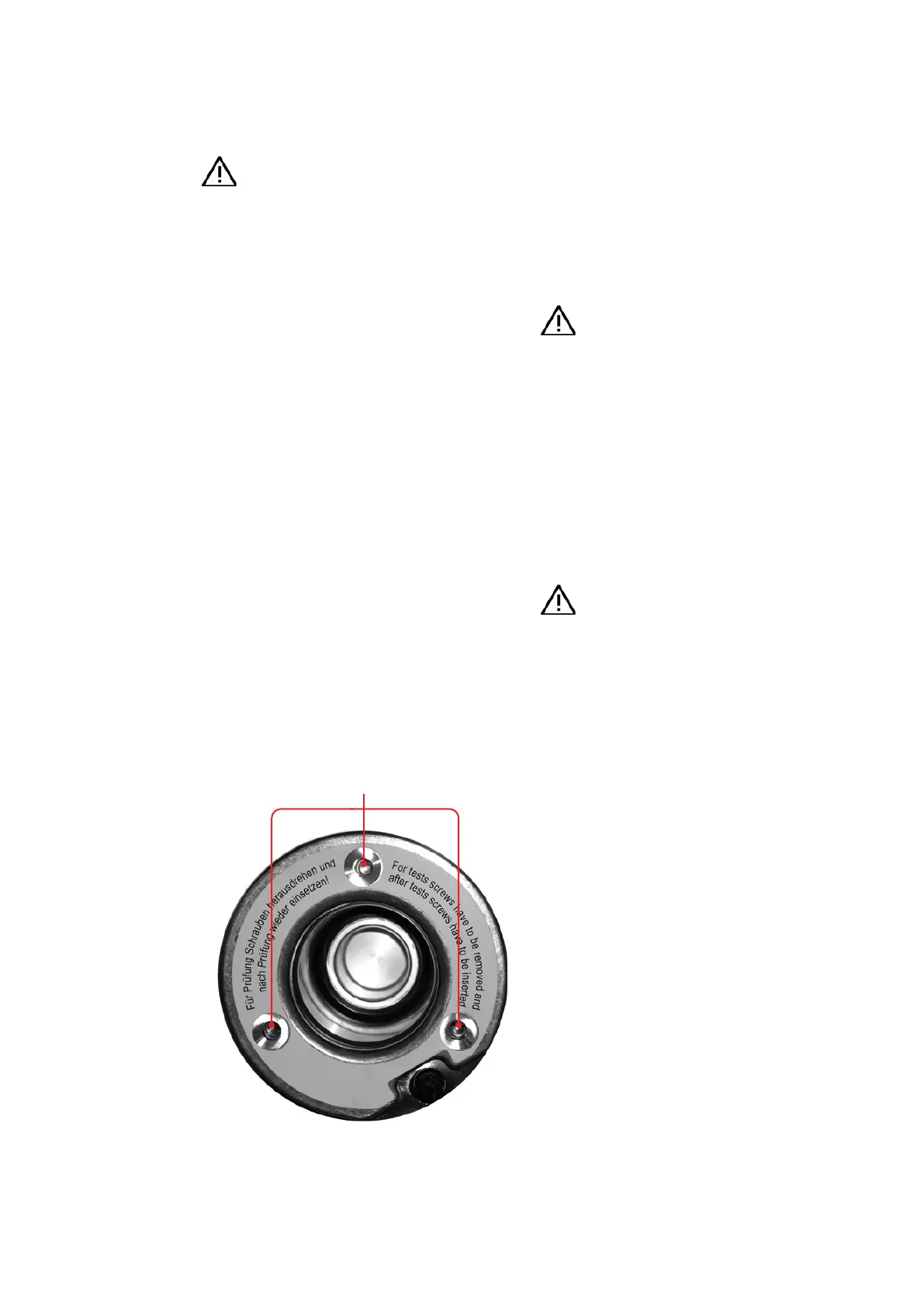
Important note
Ground the threaded bores in the voltage
transformer sockets by fitting them with
countersunk screws, DIN 7991, M8 x 30
Clean the voltage transformer socket as
described in section 3.1.3.
• Position the assembly aid in front of the cable
termination compartment. Place the voltage
transformer on the assembly aid using the
transport shackle (a correct position is ob-
tained with the aid of two centering washers on
the assembly aid and bores in the base plate of
the voltage transformer).
• Roll the assembly aid bearing the voltage trans-
former into the intended position below the
voltage transformer sockets in the cable termi-
nation compartment and engage it with the
stop.
3.3.7.2. Installation of voltage transformers
Hazard warning
If the switchgear is in operation:
• Isolate the relevant outgoing feeder
panel before installing the voltage
transformers.
• Comply with the safety regulations of
• Test the feeder panel for the off-circuit
condition in accordance with section
5.1.
• Ground the feeder panel and secure the
working area in accordance with sec-
• Switch the mcbs(
1
-
erating mechanisms off so that the
feeder panel cannot be switched on by
remote control.
• Remove the cover from the cable termination
compartment.
• Dismantle the lower crossbeam in the cable ter-
mination compartment by removing the screws
marked in fig. 3.3.7.1.1.
• Remove the padlock from the retaining plate
(fig. 3.3.7.1.2) and slide the retaining plate to the
right. Remove the retaining plate and store the
parts for further use.
—
Fig. 3.3.7.2.1:
Socket for voltage
transformer: grounding
the threaded bores with
countersunk screws,
DIN 7991, M8 x 30
Threaded bores
1. mcb: miniature circuit breaker.