3. INSTALLATION OF THE SWITCHGEAR AT SITE 43
• Crank the assembly aid up to the stop
(= baseplate of the voltage transformer),
ensuring that the centerring washers in the
assembly aid are in line with the bores in the
base plate of the voltage transformer.
• Disengage the locking plate by sliding the lock-
ing knob to the right (fig. 3.3.7.1.4). The locking
plate is pressed outwards by approx. 0.8 inches,
thus releasing the voltage transformer.
• Crank the voltage transformer down until the
stop is reached. (fig. 3.3.7.1.7).
• Disengage the assembly aid (fig. 3.3.7.1.7) and
roll the assembly aid with voltage transformer
out of the panel.
• Lift the voltage transformer off the assembly
aid using the lifting handle (fig. 3.3.7.1.8).
• Dismantle the further voltage transformers in
the same way.
• Fit the protective caps supplied to protect the
silicone insulating parts of the voltage
transformers from soiling and damage.
• Close off the open voltage transformer sockets
with insulating blanking plugs prior to bringing
the panel on line or performing high voltage
testing.
• Refit the lower crossbeam in the cable
termination compartment (fig. 3.3.7.1.2).
• Hang the cover of the cable termination
compartment in position and screw the cover
tight.
—
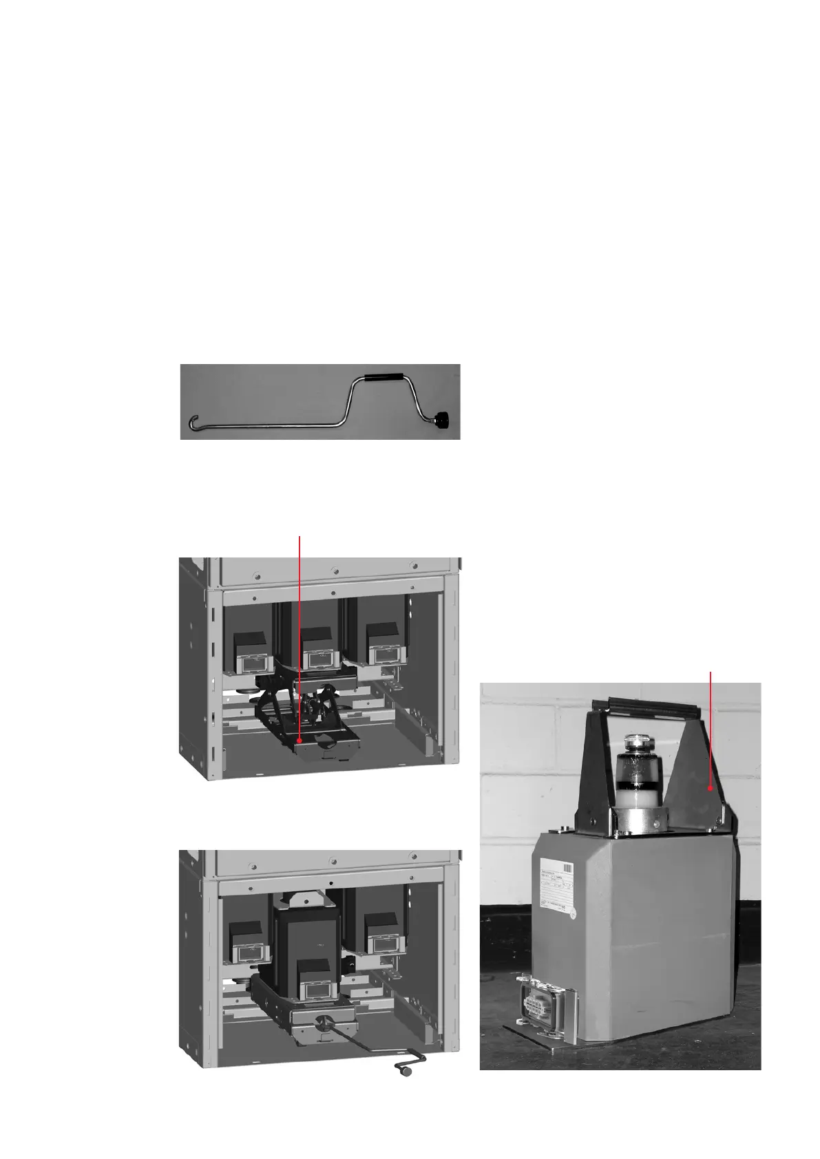
Fig. 3.3.7.1.6:
Assembly aid (also
named “VT-truck
compact”) in the
cable termination
compartment beneath
a voltage transformer
—
Fig. 3.3.7.1.7:
Disengaging the
assembly aid
—
Fig. 3.3.7.1.8:
Voltage transformer
with lifting handle
Assembly aid
Lifting handle
—
Fig. 3.3.7.1.5
—
Fig. 3.3.7.1.6
—
Fig. 3.3.7.1.7
—
Fig. 3.3.7.1.8
—
Fig. 3.3.7.1.5:
Crank for assembly aid