24 ZX2 GAS-INSULATED MEDIUM VOLTAGE SWITCHGEAR
Important note
Do not press the valve pin
3
(Fig.
out of the valve.
• Pull the locking ring (
4
in Fig. 3.3.1.1.3) of the
manometer coupling piece towards the
manometer, push the coupling piece onto the
filling connector up to the stop and slide the
locking ring towards the filling connector.
• Check the reading on the scale of the pressure
gauge.
Important note
The reading must be in the green area of
the instrument’s scale. If it is not, or if
the site altitude is greater than 1000 m,
please contact us.
• Pull the locking ring of the manometer coupling
piece towards the manometer and pull the
manometer from the filling connector.
• Screw the protective cap onto the filling
connector.
3.3. Assembly of the switchgear
3.3.1. Preparatory work
3.3.1.1. Checking the SF
6
pressure in the gas
compartments
Each panel may consist of one to three gas
compartments, depending on the version (see
manual HB 645 en). Each gas compartment is
fitted with one filling connector.
There are two different types of filling valves. The
handling procedures differ from each other.
The filling connectors for the circuit-breaker
compartment and the front busbar compartment
are located in the low voltage compartment and
are accessible from the front when the low
voltage compartment door is open.
The filling connector for the rear busbar
compartment is located behind the top rear cover.
Check the gas pressure in each gas compartment
with a temperature-compensated pressure gauge
(see list of tools) before aligning and connecting
the panels, as follows in the next two chapters.
• Dismantle the rear covers on the rear busbar
compartments if fitted.
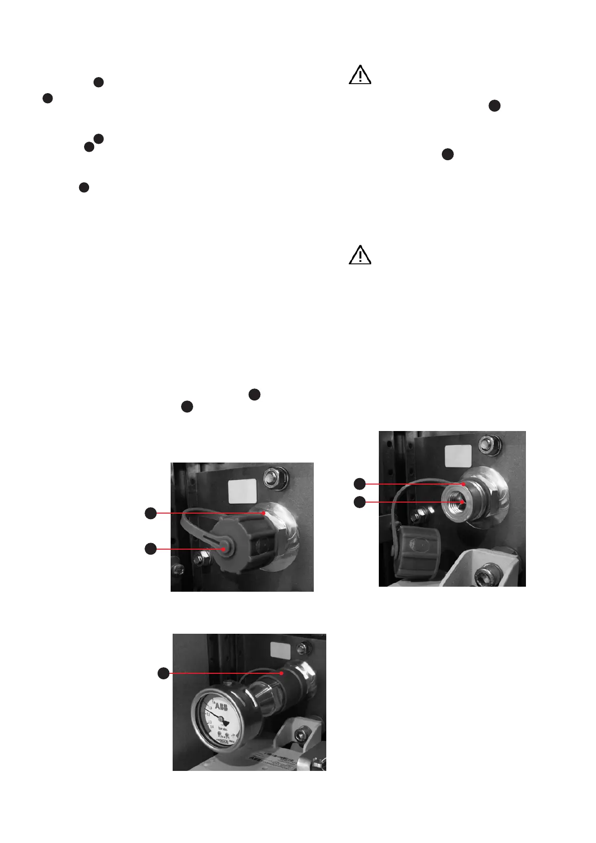
• Remove the protective cap
2
from the filling
connector
1
by turning it counter-clockwise
(Fig. 3.3.1.1.1.1).
—
Fig. 3.3.1.1.1:
Filling connector
1
with protective cap
2
in the low voltage
compartment
—
Fig. 3.3.1.1.2:
Filling connector
1
with valve pin
3
—
Fig. 3.3.1.1.1.1
—
Fig.3.3.1.1.1.2
—
Fig. 3.3.1.1.1.3
—
Fig. 3.3.1.1.3:
Filling connector
with pressure gauge,
locking ring
4
1
2
1
3
4