96 ZX2 GAS-INSULATED MEDIUM VOLTAGE SWITCHGEAR
• Establish the test configuration in accordance
with the manufacturer’s instructions for the
protection testing equipment and perform the
protection test.
• Ground the switchgear section after completion
of the test.
• Immediately on completion of testing, remove
the current testing plugs and replace them with
the intended devices (voltage transformers,
surge arresters or blanking plugs).
• Refit the cover on the cable termination
compartment.
Panels with outer cone
Direct access to the conductors for performance
of protection tests by primary current injection is
possible via the fitted cable connectors. The test
current is applied via suitable testing sets for the
cable connector system used.
• Dismantle the cover on the cable termination
compartment of the relevant panel.
• Fit the testing set in accordance with the
manufacturer’s instructions.
• Establish the test configuration in accordance
with the manufacturer’s instructions for the
protection testing equipment and perform the
protection test.
• Ground the switchgear section after completion
of the test.
• Remove the testing set.
• Refit the insulating ends of the cable
connectors in accordance with the
manufacturer’s instructions.
• Refit the cover on the cable termination
compartment.
6.5. Protection testing by primary current
injection
Hazard warning
Comply with the safety regulations to
• Isolate the relevant switchgear section
in accordance with section 5.
• Test the switchgear section for the off-
circuit condition as described in
section 6.1.
• Ground the switchgear section and
secure the working area in accordance
• Switch the mcbs (
1
operating mechanisms off in order to
prevent the switchgear section being
energized by remote control.
• Observe the examples of primary side test
circuits in fig. 6.5.1 and 6.5.2.
Important notes
• If the circuit-breaker is also to be
tested, please note that grounding via
the circuit-breaker is cancelled when
the breaker is opened. Otherwise,
disconnect the release coil before
testing.
• Note that when the voltage signals
from the voltage transformers in the
panel to be tested are used by other
panels, the signals are not available
during the work. This can lead to
impairments of function in the other
panels.
• Do not exceed the maximum values for
the current testing plug (see the
Panels with inner cone
Direct access to the conductors for performance
of protection tests by primary current injection is
possible via current testing plugs which are fitted
to the test sockets of the panel.
• Dismantle the cover on the cable termination
compartment of the relevant panel.
• Dismantle any voltage transformers fitted as
described in section 2.3.6, and also any surge
arresters or blanking plugs on the test sockets
of the relevant outgoing feeder.
• Clean the current testing plug.
• Insert the current testing plugs into the test
sockets and screw the plugs to the sockets.
—
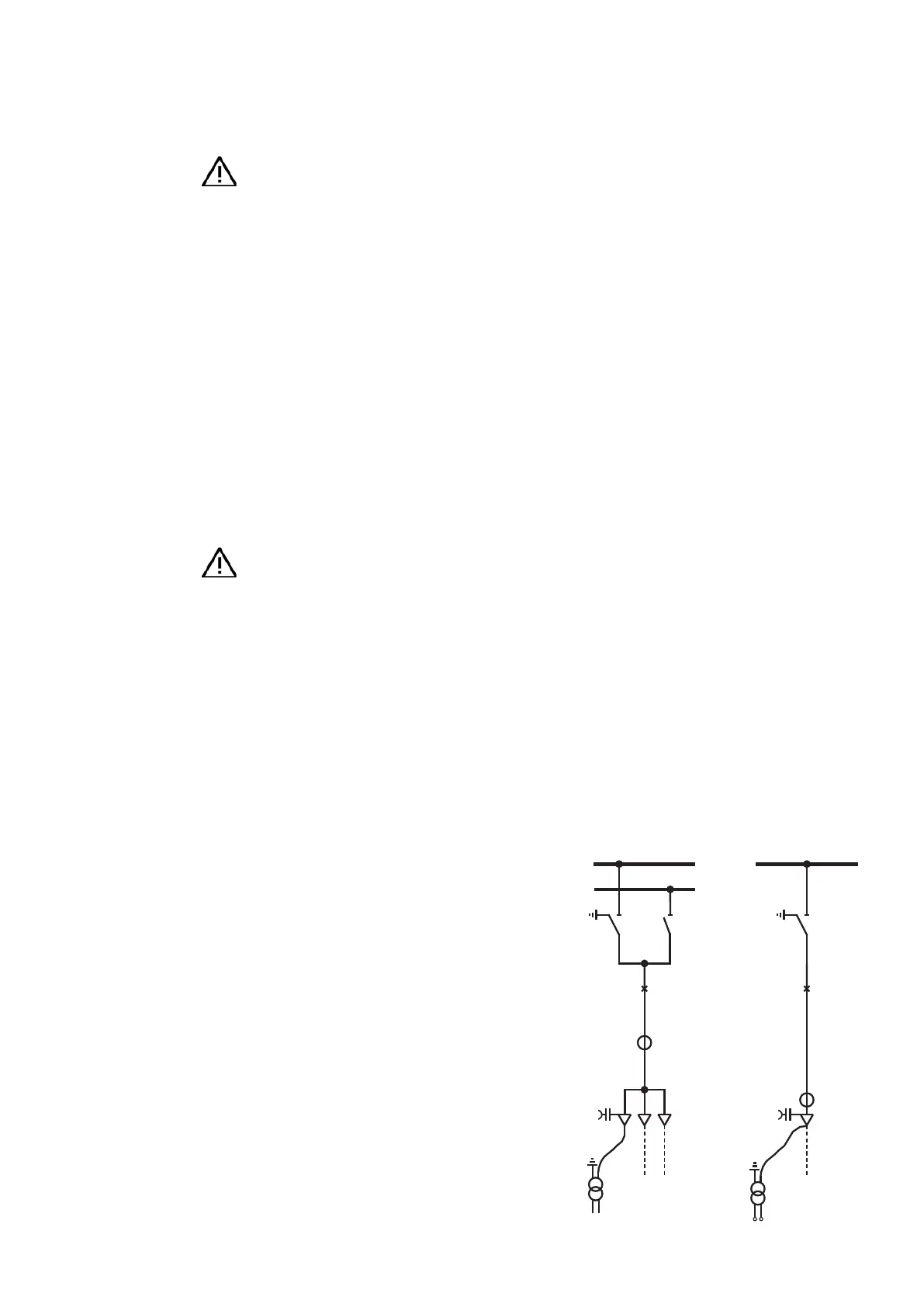
Fig. 6.5.1:
Panel with inner cone,
test transformer con-
nected to the test socket
via a current testing
plug, current flow via
the current transformer
and circuit-breaker to
the grounding contact
of the three-posi-
tion disconnect
—
Fig. 6.5.2:
Panel with outer cone,
test transformer con-
nected to the cable con-
nector via suitable test
leads, current flow via
the current transformer
and circuit-breaker to
the grounding contact
of the three-posi-
tion disconnect
1. mcb: miniature circuit breaker.
Test
transformer
—
Fig. 6.5.1
—
Fig. 6.5.2
Test
transformer